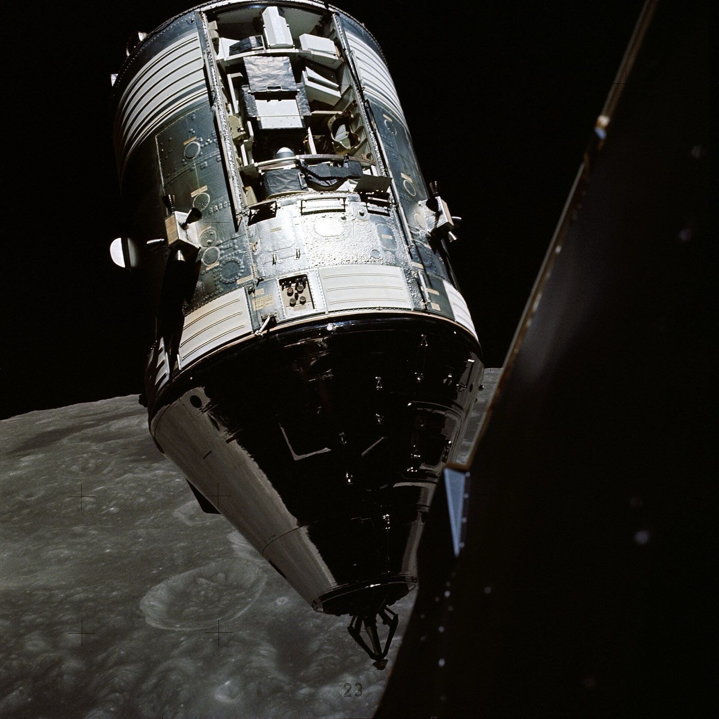
North American Aviation built the Command and Service Module for NASA. It carried three astronauts to lunar orbit and back. Only the command module, which held the crew, returned to Earth, and each flight ended in a splashdown. The cabin air was pure oxygen at 5 pounds per square inch.
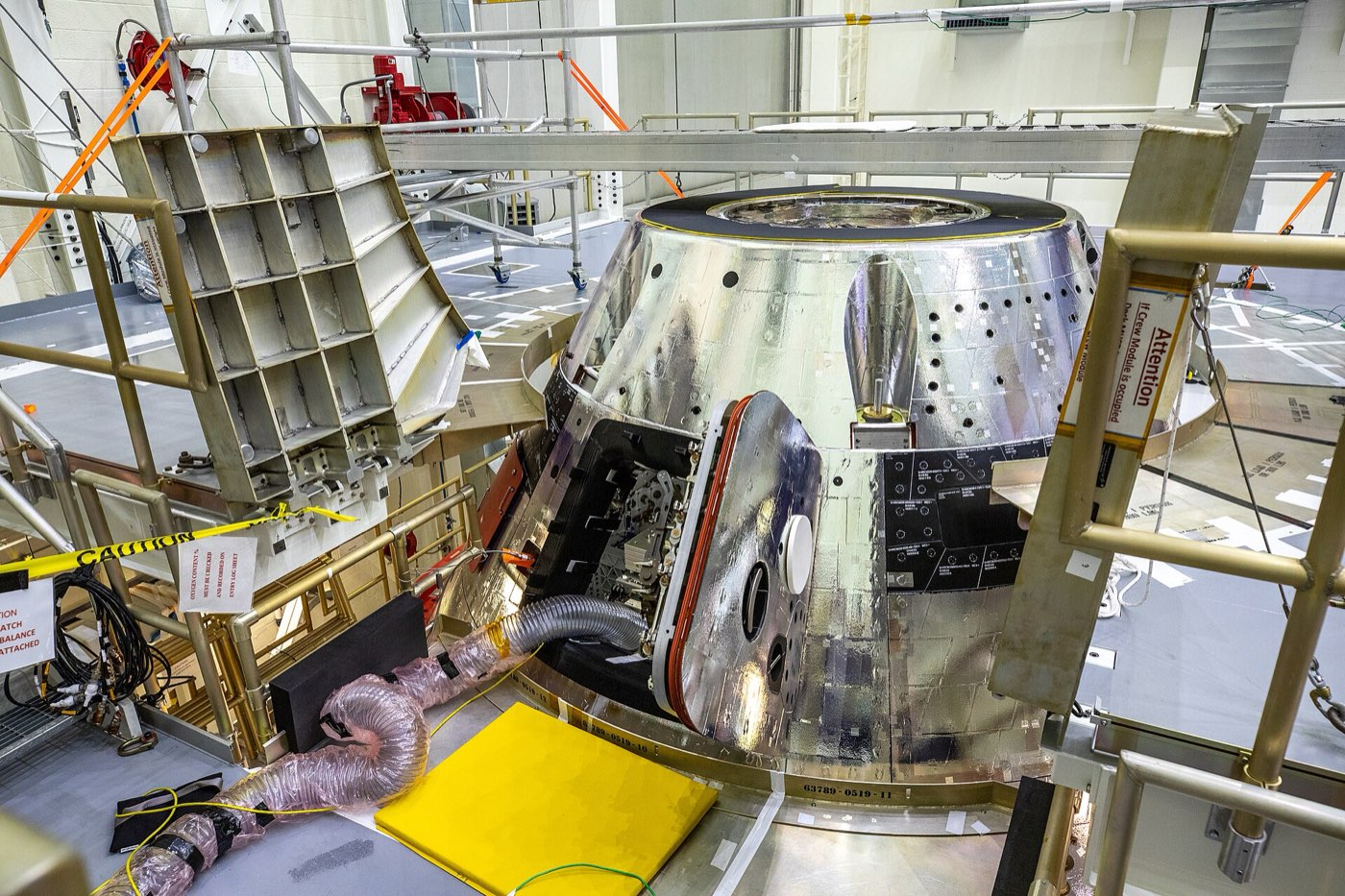
The command module has two walls. Its inner cabin is aluminium honeycomb, a cellular core sandwiched between aluminium sheets. The outer shell is the same idea in stainless steel, covered with an ablative coating. The service module carried the fuel cells, the main propulsion system and tanks of very cold hydrogen and oxygen.
Application
Apollo CSM carried three astronauts to lunar orbit and back. The command module returned at lunar-return speed, so its stainless steel honeycomb shell and ablative coating are a landmark case of reentry heat shield design.
Photos
How it is built
Command module shells
The inner pressure shell around the crew is aluminium honeycomb between aluminium alloy sheets. The outer shell is stainless steel honeycomb between stainless steel sheets, and it carries the heat shield. That is Avcoat 5026-39/HC-G, a low-density glass-filled epoxy-novolac resin held in honeycomb.
Inner pressure shell (crew compartment)
Outer shell (heat shield structure)
Ablative heat shield material
Thruster tanks and chambers
The command module had reaction control thrusters for turning the spacecraft. Their fuel and oxidiser tanks were titanium, each with a Teflon bladder to push the propellant out. The thruster chambers combined ablative parts, asbestos and a fibreglass wrap.
Fuel tanks (2)
Oxidizer tanks (2)
Propellant bladders
Thruster thrust-chamber insulation
Thruster outer wrap
Service module structure
The service module's frame included solid aluminium alloy radial beams, machined into shape. The outer panels, 1 inch thick, were aluminium honeycomb between two aluminium sheets. The VHF antennas, shaped like scimitars, were stainless steel.
Radial beams
Sector and RCS exterior panels (1 in thick)
VHF scimitar antennas
Fuel cells and gas tanks
Three fuel cell power plants supplied the primary electrical power. Spherical tanks held very cold oxygen and hydrogen. The oxygen tanks were made of Inconel and the hydrogen tanks of titanium.
Cryogenic oxygen tanks
Cryogenic hydrogen tanks
Where the parts areNumber of parts we have listed in each group
Command module structure and interior15
Launch escape system9
Command module reaction control8
Service propulsion system8
Guidance, navigation and control7
Service module5
Service module reaction control5
Earth landing system5
Command module structure3
Electrical power3
What it is made of
Aluminium honeycomb
The command module's inner pressure shell and the service module's outer panels, between aluminium sheets.
Stainless steel
The honeycomb and sheets of the command module's outer shell, and the service module's VHF antennas.
Avcoat 5026-39/HC-G
The ablative heat shield material, a low-density glass-filled epoxy-novolac held in honeycomb.
The command module's helium, fuel and oxidiser tanks, and the service module's hydrogen tanks.
Teflon
Bladders inside the command module's propellant tanks, used to push the propellant out.
Asbestos
A layer in the thrust chambers of the command module's thrusters, beside an ablative sleeve and a fibreglass wrap.
The materials by familyHow many of the parts that name a material use each one
Titanium9
Aluminium8
Stainless steel6
Other5
Glass fibre4
Polymers and foams3
Nickel and cobalt alloys3
Gold and silver1
How it connects to other things
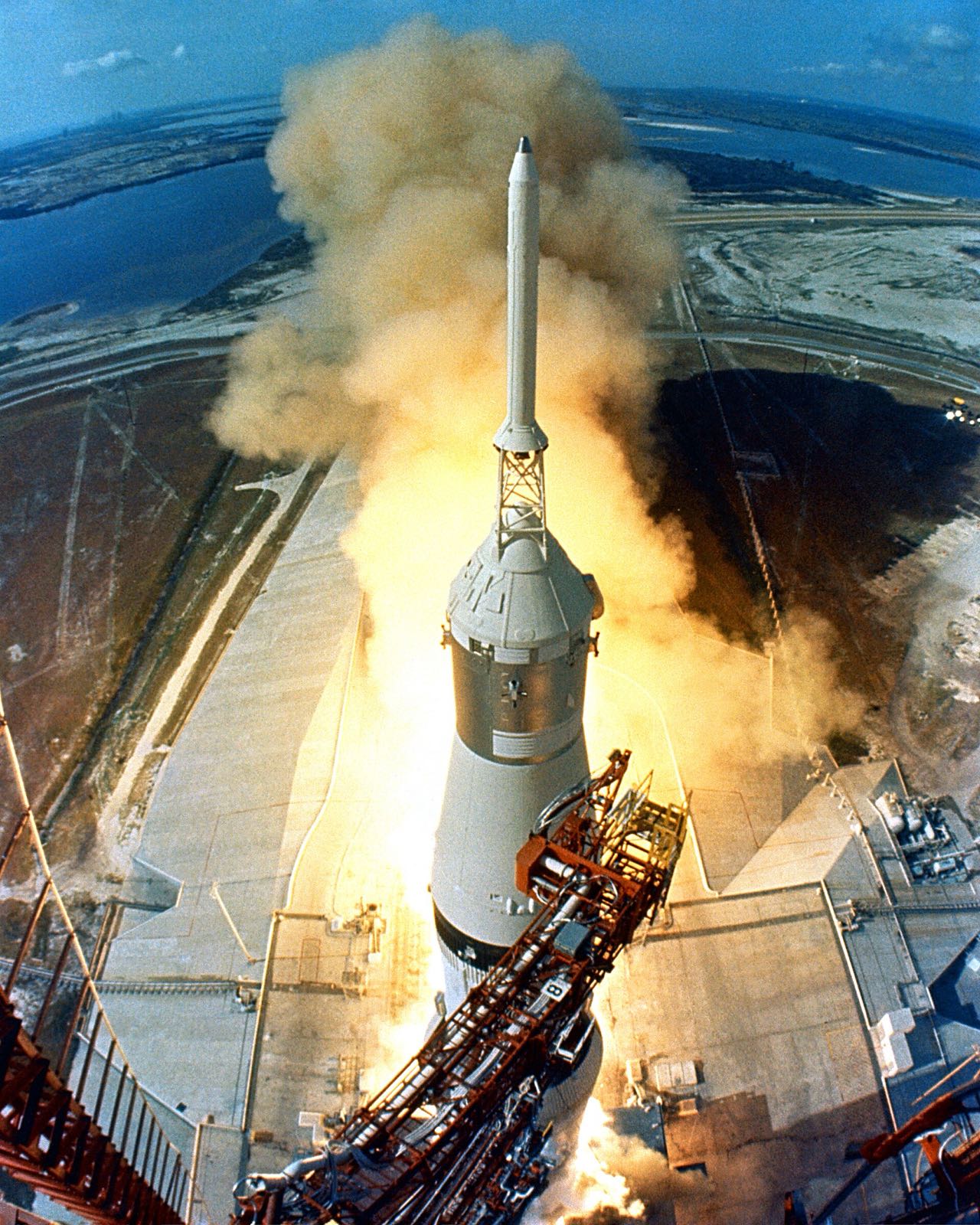
Apollo 7, the first crewed flight, launched on 11 October 1968 on a Saturn IB. Bell Aerosystems of Buffalo, New York, made the command module's propellant tanks. Beech Aircraft of Boulder, Colorado, built the service module's oxygen tanks, and Air Products & Chemical built its hydrogen tanks.
Engines
AJ10-137 engine
Service propulsion engine, Aerojet-General; one 20,500 lbf main engine in the service module
R-4D engine
Reaction control engine, Marquardt; sixteen ~100 lbf engines in four service module quads
Valve-level heritage only: a NASA technology contract to improve the Apollo SPS bipropellant valve fed the OMS valve design (the 1985 paper says the results were used to design the OMS valve)
Made or supplied by
North American Aviation (North American Rockwell)
Prime contractor; built the command and service modules
Aerojet-General Corporation
Service propulsion engine and gimbal actuators
The Marquardt Corporation
Service module R-4D reaction control engines
Rocketdyne Division, North American Rockwell
Command module SE-8 reaction control engines
Lockheed Propulsion Co.
Launch escape motor and pitch control motor
Thiokol Chemical Corp.
Tower jettison motor TE-M-380
Pratt & Whitney Aircraft
Three fuel cell power plants
Beech Aircraft
Inconel cryogenic oxygen tanks
Air Products & Chemical Co.
Titanium cryogenic hydrogen tanks
Sargent Industries (including its Airite Division)
SPS helium tanks and SM RCS helium tanks
General Motors Allison Division
SPS titanium propellant tanks
Bell Aerosystems Company
Command module and service module RCS propellant tanks
Menasco Manufacturing Co.
Command module RCS helium tanks
Honeywell, Inc.
Stabilization and control subsystem
AC Electronics Division of General Motors
Production and integration of the guidance and navigation system; IMU
MIT Instrumentation Laboratory
Guidance and navigation design; computer designer
Raytheon Co.
Built the command module computer
Kollsman Instrument Co.
Optical subsystem
Collins Radio Co.
Most telecommunications components
Aeronca Manufacturing Co.
Heat shield panels
Avco Corp.
Ablative heat shield coating
Operated by
NASA Manned Spacecraft Center (customer)
North American Rockwell built the spacecraft under a contract with NASA's Manned Spacecraft Center
Products that share an engine or part with this one
R-4D engine. Here: Reaction control engine, Marquardt; sixteen ~100 lbf engines in four service module quads. There: Reaction control thruster, Marquardt; sixteen 100 lbf thrusters in four ascent-stage clusters.
Titanium. Here: Helium tanks (2); Fuel tanks (2) and more. There: Outboard engine fairings and stabilization fins; Control pressure nitrogen bottle (2,200 cubic in) and more.
Aluminium. Here: Radial beams; Crushable ribs (x4) and more. There: S-IVB forward skirt, aft skirt, thrust structure and aft interstage.
Inconel. Here: Cryogenic oxygen tanks; Q-ball instrument package and Inconel nose cone. There: Q-ball and nose cone.
TitaniumAluminiumaluminum honeycomb between aluminum alloy sheetsInconel+1 more
Where each one is used
Titanium. Here: Helium tanks (2); Fuel tanks (2) and more. There: Some brackets and fasteners (lunar module); Descent-stage hot-area structure and more.
Aluminium. Here: Radial beams; Crushable ribs (x4) and more. There: Cabin front-face, RCS cluster trusses, decks and bulkheads; Micrometeoroid shield and more.
aluminum honeycomb between aluminum alloy sheets. Here: Inner pressure shell (crew compartment); Sector and RCS exterior panels (1 in thick). There: Primary struts with crushable aluminum-honeycomb cartridge; Footpads (x4, aluminum honeycomb).
Inconel. Here: Cryogenic oxygen tanks; Q-ball instrument package and Inconel nose cone. There: Plume-exposed shield areas; RCS plume deflector.
TitaniumAluminiumaluminum honeycomb between aluminum alloy sheetsAvcoat 5026-39/HC-G
Where each one is used
Titanium. Here: Helium tanks (2); Fuel tanks (2) and more. There: Heat shield skeleton.
Aluminium. Here: Radial beams; Crushable ribs (x4) and more. There: Pressure vessel (seven large pieces, friction-stir welded); Backbone assembly (floor structure) and more.
aluminum honeycomb between aluminum alloy sheets. Here: Inner pressure shell (crew compartment); Sector and RCS exterior panels (1 in thick). There: CFRP sandwich panel core.
The alloys of the face sheets and honeycomb cores are not named, and neither is the window glass. The main engine, fuel cells, parachutes and insulation have no published materials. Published lengths for the service module differ slightly.
The detailed data
What is written above is built from these numbers and quotes. Each row links to the page it was taken from. Get all of it as JSON, or ask our MCP server.
Features
Command module is the only part that returned to Earth
Service module carried fuel cells, cryogenic tanks and the main propulsion system
Fuel cell power plants supplied primary electrical power
Specifications
What
Value
Crew
Three astronauts
First crewed flight
Apollo 7, launched 11 October 1968 on a Saturn IB
Cabin atmosphere
100 percent oxygen at 5 psi
Habitable volume
210 cubic feet
Service module size and mass
24 ft 2 in long, 12 ft 10 in diameter, 55,000 lb loaded
Apollo spacecraft stack height
82 ft
Service module height and mass (ASME landmark record)
24 ft 9 in tall, 12 ft 10 in diameter, 54,160 lb launch weight
Mission duration
8 to 10 days from launch to Earth landing
Cabin air temperature in flight
70 to 75 F
Crew supplies carried
Items for up to 14 days
Parachute splashdown speed
32 ft/s with three main parachutes, 36 ft/s with two
Entry heating and speed
About 24,500 mph at entry, heating up to 5,000 F at the aft heat shield
Production contract scope
49 manned or test spacecraft (command and service modules)
Prime contract value (3 Feb 1968)
About 2,996,000,000 US dollars
CM RCS thrust per engine
About 93 lbf
SPS specific impulse
314 s
SPS thrust-vector range
About plus/minus 10 deg (Z) and plus/minus 6 deg (Y)
Fuel cell redundancy
Three plants normally run; two are sufficient to complete the mission
Cryogenic oxygen tank size
26 in diameter, 326 lb each
Cryogenic hydrogen tank size
31.75 in diameter, about 29 lb each
Materials in detail
Each material named in the sources: where it is used here, which other products use it, and its key numbers when its material page exists.
Command module shells and the heat shield material, plus several RCS and service module parts, have stated materials from the ASME landmark record and EngineHistory.org. Components, suppliers and links were added from public sources. A material is left blank where no source states it.
Q-ball instrument package and Inconel nose coneQ-ball senses angle of attack and dynamic pressure for abort decisions; the cone caps the escape system“The Inconel nose cone was 13.37" long”
Missing: face sheet and core alloys, window glass, service propulsion engine, fuel cell, parachute and insulation materials; standards. More detail: Not found in public sources that could be fetched: suppliers of the environmental control system, cabin fans and suit loop, waste management, food and water hardware, the launch escape and CM forward-compartment hardware beyond the motors, the parachute maker (Northrop Ventura appears in NASA TN D-7437 only as maker of a failed parachute link assembly, in a garbled appendix), the SLA builder, and the batteries and inverters. Materials not stated for most structures: the stated ones are titanium tower tubing, Buna-N insulation, Inconel nose cone, lead and depleted uranium ballast, fiberglass and cork boost cover, steel couch framing, silica window glass, molybdenum and cobalt-base R-4D parts, columbium and titanium SPS nozzle, stainless steel SPS valve balls, beryllium IMU stable member and nylon main parachute cloth. Conflicting values are listed side by side: boost protective cover 100 lb versus 700 lb, SPS thrust 20,000 versus 20,500 lbf, forward heat shield jettison 24,000 versus 25,000 ft, couch struts honeycomb versus steel wire rings, service module height 24 ft 2 in (existing entry) versus 24 ft 9 in (ASME). The Apollo 11 Press Kit and the Apollo Operations Handbook text were only readable as OCR; quotes come from cleaner enginehistory.org, NASA SP-4205 and Apollo News Reference chapters. No fetched source ties the A7L suit name to the command module, so no relation to nasa-apollo-a7l-spacesuit is given; the lunar module was not made a carries target because it docks rather than rides inside the CSM. The Apollo 11 Press Kit PDFs on nasa.gov returned 404 and the web search budget ran out before NASM object pages could be checked.