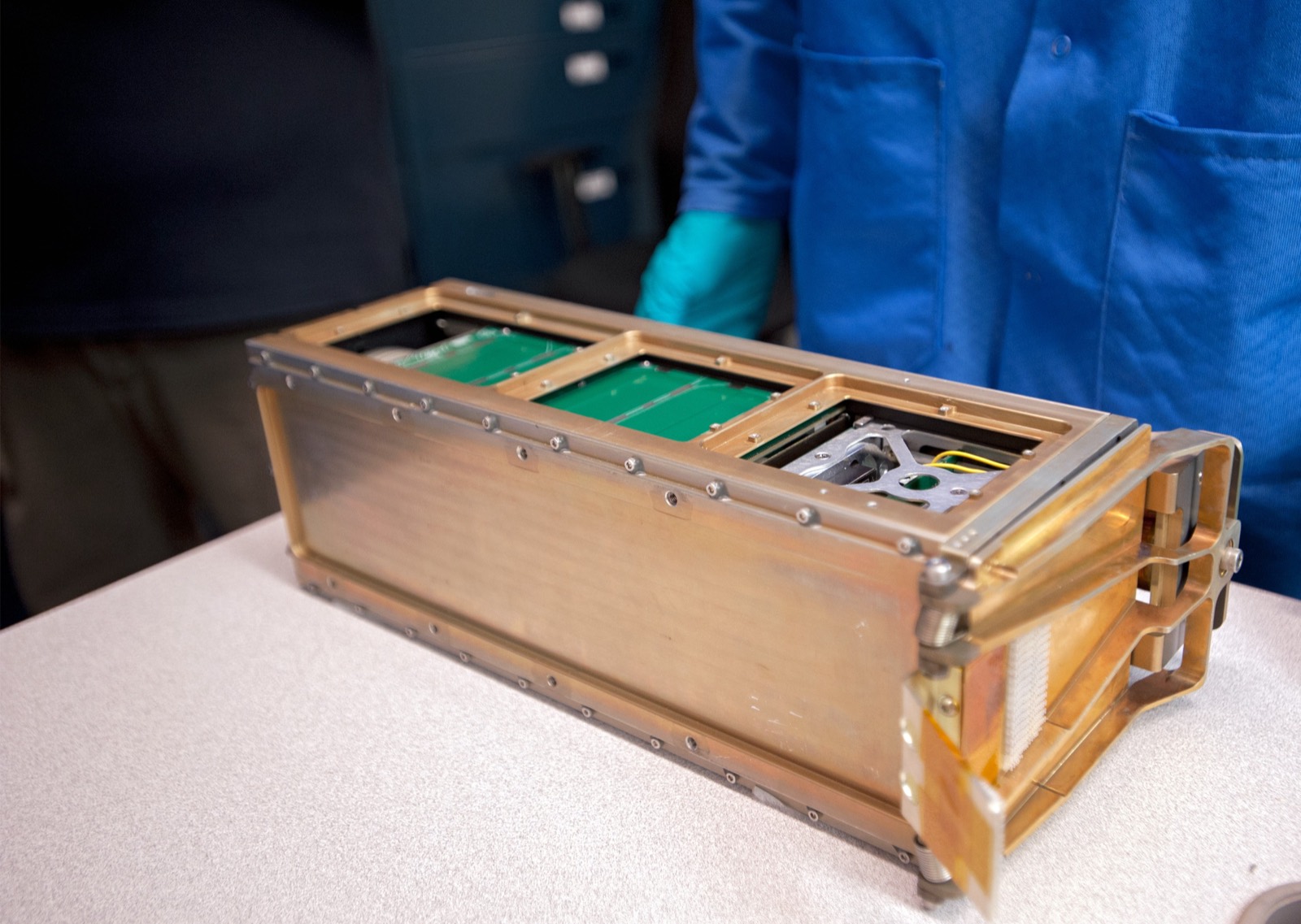
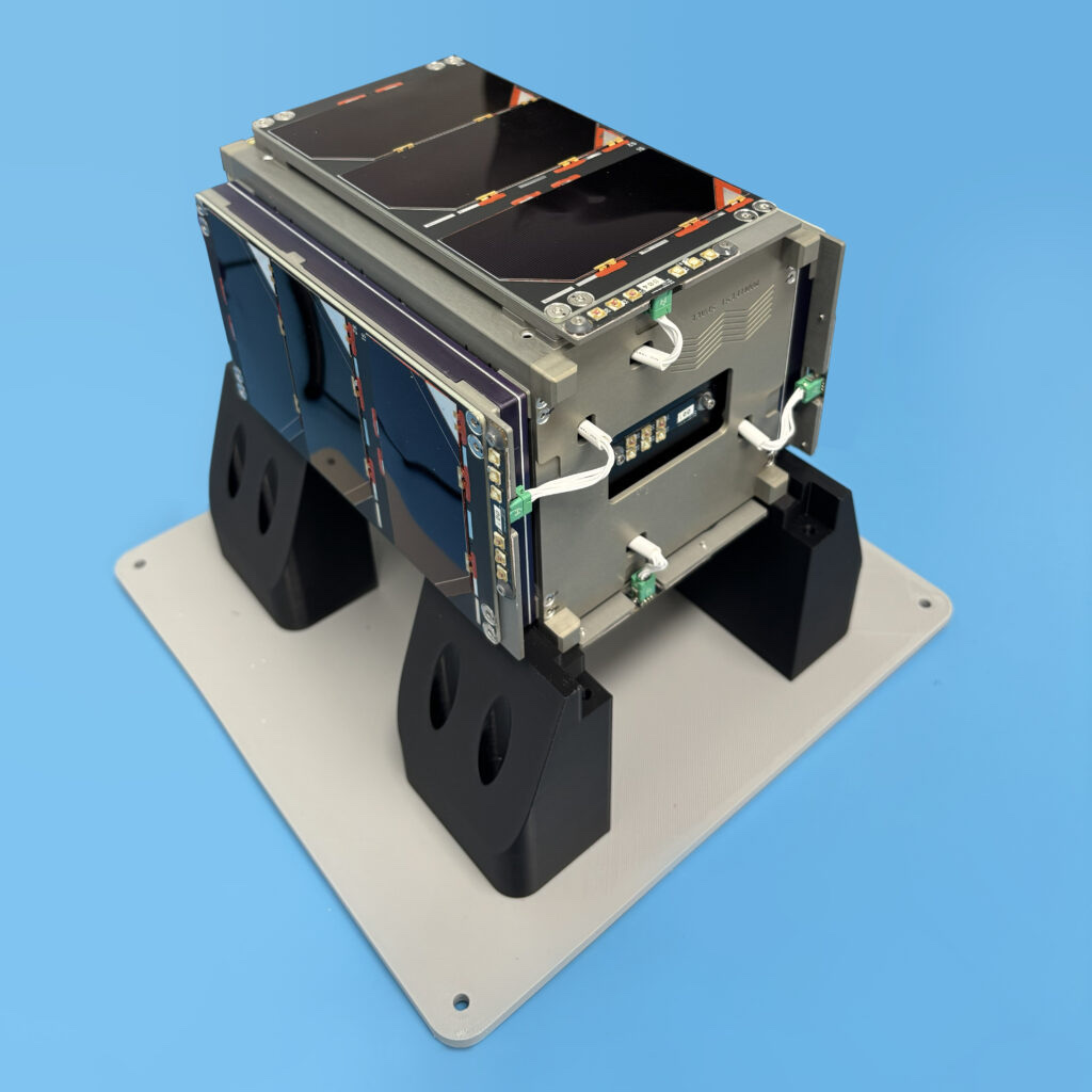
RAX-1 CubeSat on a lab bench with grey aluminium rails and dark solar-cell side panelsRAX-1, built on the kit
Pumpkin Space Systems

Pumpkin CubeSat Kit structure

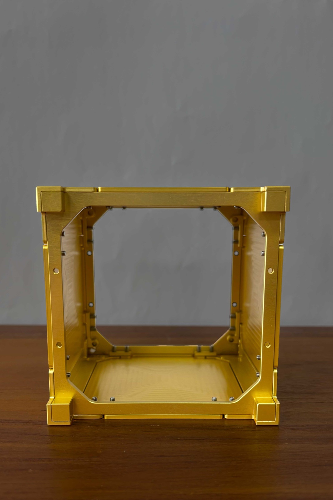
Pumpkin's CubeSat Kit structure is an aluminium frame for small satellites, held together by only ten screws.

Structures and frames
Product IDpumpkin-cubesat-kit-structure
Available lengths
0.5U, 1U, 1.5U, 2U and 3U
Fastener count
Ten M3x5mm stainless-steel flathead screws for the whole structure
1U length
113.50 mm
Complete skeletonised 1U kit mass
300 g total with flight module and transceiver
First flights by revision
Rev B 2007 (Libertad-1), Rev C 2008 (Delfi-C3), Rev D 2009 (ITU-pSAT1)

In short

Pumpkin Space Systems sells this frame for building a small satellite from commercial parts. It comes in five lengths, from 0.5U to 3U, either as a sheet-metal chassis or as a machined Pro version. A 1U frame is 113.50 millimetres long. Pumpkin says its aims were room inside, low weight and strength.

Pumpkin describes the structure as three major assemblies. Six M3 screws fasten the base plate and four fasten the cover plate. Only the chassis walls change from one size to the next. The aluminium is hard anodised where parts wear and coated with alodyne, a clear chromate finish, so the whole frame conducts electricity.

Application

A CubeSat chassis for building a small satellite from commercial parts. It is offered as a sheet-metal frame or a machined Pro frame, in sizes from 0.5U to 3U, and held together by only ten screws. Helpful for teams that want a flight-ready structure with a defined finish and plating instead of designing their own.

How it is built

Chassis walls

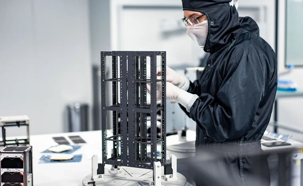
The standard walls are 5052-H32 aluminium sheet, joined at one riveted edge, and Pumpkin says the one-piece design resists compression and twist. Solid and skeletonised versions are sold, the second with cut-outs for solar cells and sensor views. The Pro version is machined from 7075-T6 billet.

  • Chassis Walls Assembly
  • Chassis Walls, solid-wall version (0.5U to 3U)
  • Chassis Walls, skeletonized version (0.5U to 3U)
  • Machined chassis components (CubeSat Kit Pro)
  • Riveted edge of the Chassis Walls

Base and cover plates

Both plates are 5052-H32 aluminium. The base plate closes the end where the motherboard sits and carries one or two separation switches, which tell the satellite it has left its dispenser. Cover plates come in other forms, one for up to four switches and one with an 88 millimetre central cut-out.

  • Base Plate Assembly (solid-wall or skeletonized)
  • Cover Plate Assembly (solid-wall or skeletonized)
  • Separation switches in the base plate (single or dual)
  • Quad-switch Cover Plate Assembly
  • Large Aperture Cover Plate Assembly

Screws, rods and spacers

Every fastener is non-magnetic stainless steel. Four threaded rods and aluminium spacers hold the stack of circuit boards in compression. Four small standoffs of 7075-T6 aluminium tie the rods to the chassis.

  • Chassis screws (ten per structure, M3x5mm flathead)
  • All fasteners, captive and loose
  • Threaded rods, M3 stainless (x4)
  • Through-hole spacers, aluminium, 15.24 mm x 6.0 mm OD (x16)
  • Midplane Standoffs A, B, C, D and four M3x5 mm screws

Feet and solar clips

The corner feet are machined from 7075-T6 aluminium and hard anodised. An option adds spring plungers to them, which push a neighbouring satellite away in a shared dispenser. A set of eight stainless-steel clips holds solar panels on all six sides without extra fasteners, adding 9 grams.

  • Feet
  • Separation plungers in the corner feet (option)
  • Solar Panel Clips Set (P/N 711-00346, 7 + 1 clips)

Payload sections

An adapter plate joins a machined external payload section to the sheet-metal chassis, and a payload cover plate closes the far end. Sections run from 0.5U to 2.5U in length. Both plates are 5052-H32 aluminium, and the section's edge rails are hard anodised.

  • Payload Adapter Plate
  • Payload Cover Plate Assembly
  • External payload edge rails
Where the parts areNumber of parts we have listed in each group
  • Module-stack hardware (Rod & Spacer Kit)7
  • Kit electronics carried in the structure6
  • Base plate assemblies5
  • Cover plate assemblies5
  • Chassis walls4
  • Dispenser interface (control drawing 810-00252)4
  • Chassis (machined CubeSat Kit Pro)3
  • Fasteners and hardware3
  • External payload interface (optional parts)3
  • External payload plates3

What it is made of

  • Aluminium alloy 5052-H32

    The sheet-metal walls, the base and cover plates, and the payload adapter and cover plates.

  • Aluminium alloy 7075-T6

    The machined Pro chassis, the corner feet and the midplane standoffs.

  • Non-magnetic stainless steel

    Every fastener, including the ten chassis screws.

  • Stainless steel

    The threaded rods, nuts and solar panel clips. The grade is not given.

  • Aluminium

    The spacers between circuit boards. The alloy is not given.

The materials by familyHow many of the parts that name a material use each one
  • Other14
  • Aluminium9
  • Stainless steel7

How it connects to other things

Pumpkin's drawing 810-00252 sets out the CubeSat dimensions the kit conforms to. The kit fits Cal Poly's P-POD dispenser, which takes up to 3U. Delfi-C3, a 3U satellite from TU Delft, launched on India's PSLV in 2008 with X-POD dispensers. The earliest flight Pumpkin names is Libertad-1, launched from Baikonur in 2007. GOLIAT flew on the maiden flight of ESA's Vega rocket in 2012.

Used in

  • Libertad-1 (Colombia, 1U, Rev B)

    Launched from Baikonur on 17 April 2007; operated 34 days on primary batteries

  • HawkSat-1 (1U, Rev C)

    Launched from NASA Wallops on 19 May 2009

  • ITU-pSAT1 (1U, Rev D)

    First Rev D kit launched; PSLV-C14, 23 September 2009

  • GOLIAT (Romania, 1U, Rev D skeletonized)

    Vega maiden flight, 13 February 2012; reaction wheels built into the chassis walls

  • Caerus / Mayflower (payload end, 1U Rev D skeletonized)

    Falcon 9, 8 December 2010

  • Delfi-C3 (TU Delft, 3U, Rev C)

    PSLV-C9, 28 April 2008

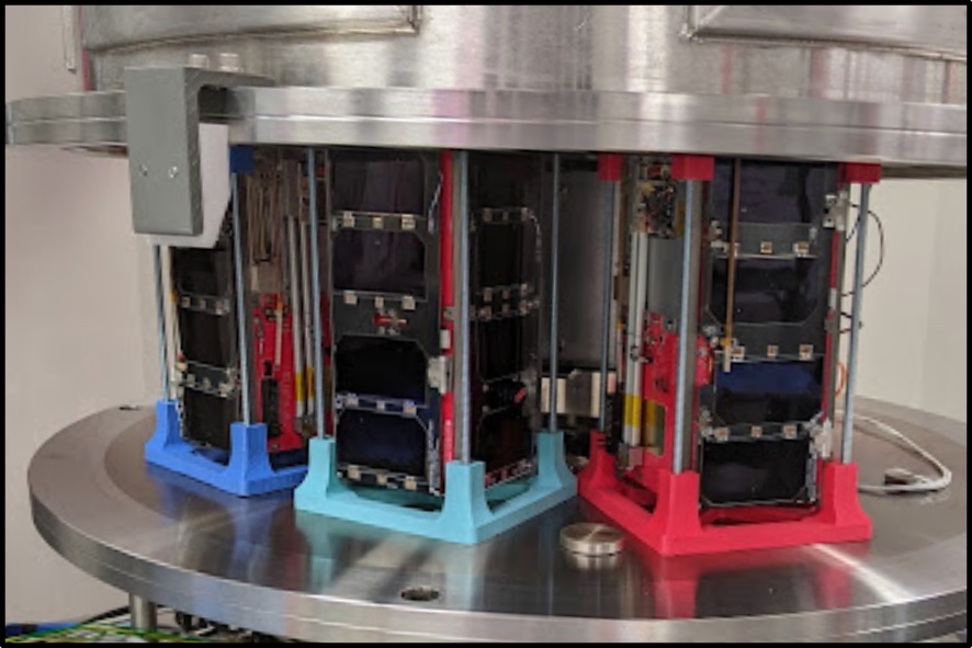
  • Radio Aurora Explorer, RAX (3U, Rev D skeletonized)

    Minotaur IV, STP-S26, 19 November 2010

  • RAX-2 (3U, Rev D skeletonized)

    Delta II with NPP, 28 October 2011; deployed from P-POD 3

  • CSSWE (3U, Rev D solid-wall)

    Atlas V, ELaNa VI, 13 September 2012

  • QbX1 and QbX2 (Colony I, MISC 2 carrier)

    MISC 2 carrier proves the CubeSat Kit External Payload scheme; Falcon 9, 8 December 2010

  • Aeneas (Colony I C1B bus, modified MISC 2)

    Atlas V, ELaNa VI, 13 September 2012

  • LMRST-Sat (JPL/Stanford 3U)

    ADACS Payload Walls plus 1.5U chassis walls were used; flight outcome not stated on the page

Carries

  • ISIS Antenna System (AntS)

    Dedicated base and cover plates take the third-party AntS deployable antenna

Launched on

  • P-POD (Poly-Picosatellite Orbital Deployer, Cal Poly)

    Compatible deployer; total kit length must not exceed 3U when deployed from a P-POD; RAX-2 flew from P-POD 3

  • X-POD (SFL/UTIAS CubeSat deployer)

    Delfi-C3 (Pumpkin Rev C 3U structure) was integrated with the X-POD deployers on PSLV-C9

  • RocketPod adapter kit (1U only)

    Pumpkin adapter kit compatible only with 1U CubeSat Kits

  • Falcon 9

    SpaceX

    Launched 8 December 2010 from Cape Canaveral

  • Atlas V

    United Launch Alliance

    Launched 13 September 2012 from Vandenberg; CSSWE flew on a Pumpkin Rev D 3U structure

  • Delta II with NPP (RAX-2)

    28 October 2011 from Vandenberg

  • Minotaur IV, STP-S26 (RAX)

    19 November 2010 from Kodiak

  • PSLV-C9 (Delfi-C3)

    28 April 2008 from Sriharikota

  • PSLV-C14 (ITU-pSAT1)

    23 September 2009 from India

  • Vega maiden flight (GOLIAT)

    13 February 2012 from Kourou

Built on

  • CubeSat Design Specification (Cal Poly)

    Interface standard; plating and dimensions follow it

  • Cal Poly CubeSat specification drawing (Pumpkin control drawing 810-00252)

    Pumpkin's CDS-derived dimensional drawing that the kit conforms to

  • CubeSat 101

    NASA CubeSat Launch Initiative

    Reference for the CubeSat Design Specification and P-POD; the guide does not name this product

Products that use the same materials

  • Atlas V

    United Launch Alliance

    stainless-steelAluminium alloy 7075-T6Aluminium
    Where each one is used

    stainless-steel. Here: Chassis screws (ten per structure, M3x5mm flathead); Threaded rods, M3 stainless (x4) and more. There: Centaur propellant tanks.

    Aluminium alloy 7075-T6. Here: Machined chassis components (CubeSat Kit Pro); Feet and more. There: Aft transition structure ring frames and skins.

    Aluminium. Here: Structure, three major assemblies; Through-hole spacers, aluminium, 15.24 mm x 6.0 mm OD (x16) and more. There: Booster LO2 and RP tanks; Propellant feedlines and more.

  • NASA small spacecraft structures review

    NASA Ames

    Aluminium alloy 5052Aluminium alloy 7075-T6
    Where each one is used

    Aluminium alloy 5052. Here: Chassis Walls Assembly; Chassis Walls, solid-wall version (0.5U to 3U) and more. There: Pumpkin CubeSat Kit structures (sub-1U to 12U SUPERNOVA).

    Aluminium alloy 7075-T6. Here: Machined chassis components (CubeSat Kit Pro); Feet and more. There: EnduroSat structures (1U to 6U); EnduroSat 1U structure and more.

  • Proba-V

    ESA

    Aluminium alloy 7075-T6Aluminium
    Where each one is used

    Aluminium alloy 7075-T6. Here: Machined chassis components (CubeSat Kit Pro); Feet and more. There: Edge profiles and hot inserts.

    Aluminium. Here: Structure, three major assemblies; Through-hole spacers, aluminium, 15.24 mm x 6.0 mm OD (x16) and more. There: Telescope (structure and mirrors, 3 telescopes).

  • Apollo Lunar Module (LM)

    Grumman / NASA

    Aluminium alloy 7075-T6Aluminium
    Where each one is used

    Aluminium alloy 7075-T6. Here: Machined chassis components (CubeSat Kit Pro); Feet and more. There: Ascent-stage structure (major alloy); Descent-stage main structure (beams, decks, bulkheads).

    Aluminium. Here: Structure, three major assemblies; Through-hole spacers, aluminium, 15.24 mm x 6.0 mm OD (x16) and more. There: Cabin front-face, RCS cluster trusses, decks and bulkheads; Micrometeoroid shield and more.

  • Apollo Command and Service Module

    North American Aviation

    stainless-steelAluminium
    Where each one is used

    stainless-steel. Here: Chassis screws (ten per structure, M3x5mm flathead); Threaded rods, M3 stainless (x4) and more. There: Outer shell (heat shield structure); VHF scimitar antennas and more.

    Aluminium. Here: Structure, three major assemblies; Through-hole spacers, aluminium, 15.24 mm x 6.0 mm OD (x16) and more. There: Radial beams; Crushable ribs (x4) and more.

  • Saturn V

    NASA

    Aluminium alloy 7075-T6Aluminium
    Where each one is used

    Aluminium alloy 7075-T6. Here: Machined chassis components (CubeSat Kit Pro); Feet and more. There: Thrust structure skin panels; Intertank and more.

    Aluminium. Here: Structure, three major assemblies; Through-hole spacers, aluminium, 15.24 mm x 6.0 mm OD (x16) and more. There: S-IVB forward skirt, aft skirt, thrust structure and aft interstage.

What we do not know

The structure page gives no weight for the bare frame, no load or vibration ratings and no temperature range. It doesn't say which alloy goes with which size, beyond sheet metal against Pro, or which metals plate the contact surfaces. Its copyright line runs 2000 to 2013, so some details may be dated.

The detailed data

What is written above is built from these numbers and quotes. Each row links to the page it was taken from. Get all of it as JSON, or ask our MCP server.

Features

  • Design drivers: maximal internal volume, lightness, strength
  • Contact surfaces can be plated to meet the CDS
  • Non-magnetic fasteners and good EM shielding sought
  • Based on precision sheet-metal fabrication with machined elements
  • All sizes share common parts
  • Monolithic chassis walls resist compression and twist
  • Accepts external payloads via an External Payload Specification
  • Approach described as space-proven; used in MISC 2 bus under NRO Colony I

Specifications

WhatValue
Available lengths0.5U, 1U, 1.5U, 2U and 3U
Size variationOnly the Chassis Walls Assembly differs between sizes
Fastener countTen M3x5mm stainless-steel flathead screws for the whole structure
Design standardPlating/finish to meet the CubeSat Design Specification (CDS)
Hard anodize specMIL-A-8625F Type III Class 1, 0.0005 in min to 0.0008 in max
Clear chromate specMIL-DTL-5541F Type II Class 1A, RoHS compliant
Complete skeletonized 1U kit mass (flyer)300 g total with flight module and transceiver
System chart: mass allotment printed with each size (not the empty structure mass)0.5U 500 g, 1U 1000 g, 1.5U 1500 g, 2U 2000 g, 3U 3000 g
System chart: overall length of each size0.5U 56.75 mm, 1U 113.50 mm, 1.5U 170.25 mm, 2U 227.00 mm, 3U 340.50 mm
External payload section lengths0.5U 55.22 mm, 1U 111.97 mm, 1.5U 168.72 mm, 2U 225.47 mm, 2.5U 282.22 mm
Flight component rating (flyer)-40 to +85 C
Control drawing: 1U length113.50 mm
Control drawing: tolerance, no decimal place0.50 mm
Control drawing: tolerance, one decimal place0.25 mm
Control drawing: tolerance, two decimal places0.10 mm
First flights by revisionRev B 2007 (Libertad-1), Rev C 2008 (Delfi-C3), Rev D 2009 (ITU-pSAT1)
CDS Rev 14.1: rail minimum width8.5 mm, measured from the rail edge to the first protrusion
CDS Rev 14.1: rail surface roughnessless than 1.6 micrometres (a 'should')
CDS Rev 14.1: rail edge radiusat least 1 mm (a 'should')
CDS Rev 14.1: rail end contact area6.5 mm x 6.5 mm minimum on the +/- Z face
CDS Rev 14.1: protrusion limit6.5 mm normal to the surface from the plane of the rail
CDS Rev 14.1: rail contact with dispenserat least 75% of the rail
CDS Rev 14.1: structure materialaluminium alloy; 7075, 6061, 6082, 5005 and/or 5052 typical
CDS Rev 14.1: rail surface finishhard anodized wherever it touches the dispenser rails
CDS Rev 14.1: maximum mass per size1U 2.00 kg, 1.5U 3.00 kg, 2U 4.00 kg, 3U 6.00 kg, 6U 12.00 kg, 12U 24.00 kg
CDS Rev 14.1: separation spring guidelinemax force below 6.7 N (1.5 lbf), stroke above 2.5 mm
CDS Rev 14.1: deployment switchat least one, actuated while the CubeSat is in the dispenser
CDS Rev 14.1: outgassingTML at most 1.0 % and CVCM at most 0.1 %
CDS Rev 14.1: remove-before-flight pinrequired; protrudes no more than 6.5 mm from the rail surface when fully inserted

Materials in detail

Each material named in the sources: where it is used here, which other products use it, and its key numbers when its material page exists.

  • Aluminium alloy 5052

    Used in 12 partsChassis Walls Assembly · Chassis Walls, solid-wall version (0.5U to 3U) · Chassis Walls, skeletonized version (0.5U to 3U) · +9 more

    Strength by temper
    13 ksi (O) to 37 ksi (H38) yield
    Typical strength in H32
    193 MPa yield, 228 MPa ultimate
    Stiffness and weight
    2.68 g/cc and 70.3 GPa
  • stainless-steel

    stainless-steel

    Used in 5 partsChassis screws (ten per structure, M3x5mm flathead) · Threaded rods, M3 stainless (x4) · M3 stainless nuts (x5) and split washers (x5) · +2 more

    Material page coming soon
  • Aluminium alloy 7075-T6

    Used in 4 partsMachined chassis components (CubeSat Kit Pro) · Feet · Midplane Standoffs · +1 more

    Tensile strength
    572 MPa
    Density
    2.80 Mg/m3
    Heat conduction
    130 W/m·K
  • Aluminium

    Used in 3 partsStructure, three major assemblies · Through-hole spacers, aluminium, 15.24 mm x 6.0 mm OD (x16) · Through-hole spacers, aluminium, 24 mm x 6.0 mm OD (x4)

    Weight
    2.7 g/cm3
    Electrical conduction
    2.6458 µΩ·cm
    Heat conduction
    220 W/(m·K)
    Also in 33 other products
  • nonmagnetic stainless steel

    stainless-steel-nonmagnetic

    Used in 1 partAll fasteners, captive and loose

    Material page coming soon
  • Stainless steel body with Delrin (acetal) nose

    delrin-acetal

    Used in 1 partSpring plungers (x2), stubby, Delrin nose (Vlier SSMD-51A)

    Material page coming soon

Every part we have

The page names several parts (sheet chassis walls, machined chassis, feet, standoffs, screws, spacers) with a material for each, but gives no itemised parts list with part numbers per material. Components, suppliers and links were added from public sources. A material is left blank where no source states it.

Material IDs

aluminium-5052aluminium-7075stainless-steelstainless-steel-nonmagneticaluminiumdelrin-acetal
Chassis walls (sheet-metal CubeSat Kit)1
PartMaterialFinish and standardMade by
Chassis Walls Assembly“Sheet-metal CubeSat Kit chassis components are fabricated from 5052-H32 Aluminum sheet metal, hard-anodized and alodyned as required to meet the CDS.” 5052-H32 Aluminum sheet metalaluminium-5052 hard-anodized and alodyned as required to meet the CDS · MIL-A-8625F Type III Class 1 —
Chassis (machined CubeSat Kit Pro)3
PartMaterialFinish and standardMade by
Machined chassis components (CubeSat Kit Pro)“Machined CubeSat Kit Pro chassis components are fabricated from 7075-T6 billet Aluminum, hard-anodized and alodyned as required to meet the CDS.” 7075-T6 billet Aluminumaluminium-7075 hard-anodized and alodyned as required to meet the CDS · MIL-A-8625F Type III Class 1 —
Feet“Individually machined Aluminum components (e.g. feet and Midplane Stadoffs) are made from 7075-T6 Aluminum, and are hard-anodized.” 7075-T6 Aluminumaluminium-7075 hard-anodized · MIL-A-8625F Type III Class 1 —
Midplane Standoffs“Individually machined Aluminum components (e.g. feet and Midplane Stadoffs) are made from 7075-T6 Aluminum, and are hard-anodized.” 7075-T6 Aluminumaluminium-7075 hard-anodized · MIL-A-8625F Type III Class 1 Midplane Standoff Kit (4/4) (named on system chart; part number not unambiguously readable)
Fasteners and hardware3
PartMaterialFinish and standardMade by
Chassis screws (ten per structure, M3x5mm flathead)“only ten M3x5mm stainless-steel flathead screws are required to hold the entire structure together” stainless-steelstainless-steel — —
All fasteners, captive and loose“All fasteners (captive and loose) are made from nonmagnetic stainless steel.” nonmagnetic stainless steelstainless-steel-nonmagnetic — —
Additional hardware (e.g. inter-module spacers)“Additional hardware (e.g., inter-module spacers) are generally made from stainless steel or aluminum, with conductive platings.” stainless steel or aluminum (stated generically, per-part not given) conductive platings —
Whole-structure statements (flyer)1
PartMaterialFinish and standardMade by
Structure, three major assemblies“Rigid and lightweight aluminum construction with only three major assemblies and all-stainless fasteners. | Structure is fully alodyned for electrical conductivity. Wear surfaces are hard-anodized.” aluminum (stated generically)aluminium Structure is fully alodyned for electrical conductivity. Wear surfaces are hard-anodized. —
External payload interface (optional parts)3
PartMaterialFinish and standardMade by
Payload Cover Plate Assembly“P/N 703-00407” not stated (drawing says material: see notes; the notes are not on the public sheet) — P/N 703-00407
Payload Adapter Plate“Payload Adapter Plate 703-00398” not stated (drawing says material: see notes) — 703-00398
External payload edge rails“EDGE "RAIL" SURFACE TO | RECIEVE TYPE III HARD ANODIZE | .0005" MIN / .0010" MAX” not stated TYPE III HARD ANODIZE .0005" MIN / .0010" MAX · Type III hard anodize (specification document not named on this sheet) —
Chassis walls4
PartMaterialFinish and standardMade by
Chassis Walls, solid-wall version (0.5U to 3U)One-piece primary structural element with a 97 mm x 97 mm internal cross-section“Solid-wall and skeletonized versions are available from stock.” Al 5052-H32aluminium-5052 — Supplier: Pumpkin, Inc.
Chassis Walls, skeletonized version (0.5U to 3U)Cut-out version of the chassis walls for solar cells and sensor views“Solid-wall and skeletonized versions are available from stock.” Al 5052-H32aluminium-5052 — Supplier: Pumpkin, Inc.
Mounting holes for Midplane Standoffs (on the Chassis Walls)Pre-drilled countersunk holes on two opposing sides of the walls, about every 100 mm above the base plate“CubeSat Kit Chassis Walls in 1U, 1.5U, 2U and 3U sizes have pre-drilled mounting holes for one or more MPS Kits” Not said — Supplier: Pumpkin, Inc.
Riveted edge of the Chassis WallsJoint of the sheet-metal walls; interferes with one switch tab of the quad-switch cover plate“mechanical interference between the riveted edge of the CubeSat Kit Chassis Walls and this cover plate” Not said — Supplier: Pumpkin, Inc.
Base plate assemblies5
PartMaterialFinish and standardMade by
Base Plate Assembly (solid-wall or skeletonized)Closes the motherboard end of the structure; secured to the chassis walls by six screws“Precision constructed from Al 5052-H32 and plated according to the CubeSat Design Specification (CDS)” Al 5052-H32aluminium-5052 — Supplier: Pumpkin, Inc.
Separation switches in the base plate (single or dual)Deployment (separation) switches; second switch sits on the diagonally opposite corner“Users can choose base plates with a single separation switch (deprecated), or with dual, independent separation switches.” Not said — Supplier: Pumpkin, Inc.
Large Aperture Base Plate Assembly, Dual Switch (P/N 710-02203)Base plate with a large central opening“Precision constructed from Al 5052-H32 and plated according to the CubeSat Design Specification (CDS)” Al 5052-H32aluminium-5052 — Supplier: Pumpkin, Inc.
Base Plate Assembly for AntS Antenna (P/N 710-00960)Base plate made to take the third-party AntS deployable antenna system, with dual separation switches“made specifically to accommodate the third-party AntS deployable antenna system” Al 5052-H32aluminium-5052 — Supplier: Pumpkin, Inc.
2nd Switch (L2) Spring Upgrade Kit (P/N 711-01478)Adds spring strength to the second switch; every chassis assembly ships with it since 1 January 2017“Hardware parts to provide added spring strength to the 2nd switch (L2) on Pumpkin base plate assemblies.” Not said — Supplier: Pumpkin, Inc.
Cover plate assemblies5
PartMaterialFinish and standardMade by
Cover Plate Assembly (solid-wall or skeletonized)Closes the payload end; secured to the chassis walls by four screws“Each Cover Plate Assembly includes four corner feet.” Al 5052-H32aluminium-5052 — Supplier: Pumpkin, Inc.
Separation plungers in the corner feet (option)Plungers that push a neighbouring CubeSat away in a shared dispenser“Options include separation plungers in the feet, and additional separation switches in the feet.” Not said — Supplier: Pumpkin, Inc.
Quad-switch Cover Plate AssemblyCover plate carrying up to four independent separation / inhibit switches; four orientations“permits the use of up to four separation / inhibit switches” Al 5052-H32aluminium-5052 — Supplier: Pumpkin, Inc.
Large Aperture Cover Plate AssemblyCover plate with a central cutout for optics or antennas“four corner feet and a central cutout of 88mm diameter” Al 5052-H32aluminium-5052 — Supplier: Pumpkin, Inc.
Cover Plate Assembly for AntS AntennaCover plate made to accommodate the third-party AntS deployable antenna, dual separation switches“This version of the Cover Plate is made specifically to accommodate the third-party AntS deployable antenna system.” Not said — Supplier: Pumpkin, Inc.
External payload plates3
PartMaterialFinish and standardMade by
Payload Adapter Plate (P/N 703-00398), material now statedBulkhead between the sheet-metal chassis walls and an external machined payload; the store page gives the material that the drawing leaves as 'see notes'“Precision constructed from Al 5052-H32 and plated according to the CubeSat Design Specification (CDS), each Payload Adapter Plate” Al 5052-H32aluminium-5052 — Supplier: Pumpkin, Inc.
Payload Cover Plate Assembly (P/N 710-02070), material now statedEnd cap of a hybrid sheet-metal plus machined structure; the store page gives the material that the drawing leaves as 'see notes'“Precision constructed from Al 5052-H32 and plated according to the CubeSat Design Specification (CDS), a Payload Cover Plate Assembly” Al 5052-H32aluminium-5052 — Supplier: Pumpkin, Inc.
ADACS Payload Walls (P/N 703-00397)Three-piece wall set that mounts on an MAI-100/200 ADCS in the middle of a 3U structure“These three pieces can be mounted on an MAI-100/200 ADCS” Not said — Supplier: Pumpkin, Inc.
Module-stack hardware (Rod & Spacer Kit)7
PartMaterialFinish and standardMade by
Rod & Spacer Kit (1U 711-00839, 1.5U 711-00840, 2U 711-00841, 3U 711-00842)Four threaded rods and spacers that hold the PC/104-sized module stack in compression“a system of four threaded rods, with coaxial aluminum through-hole spacers between adjacent modules” Not said — Supplier: Pumpkin, Inc.
Threaded rods, M3 stainless (x4)Columns that carry the module stack, each affixed to the Base Plate Assembly and capped with an M3 nut“M3 SST Threaded Rod of length” Stainless steel (grade not stated)stainless-steel — Supplier: Pumpkin, Inc.
Through-hole spacers, aluminium, 15.24 mm x 6.0 mm OD (x16)Spacer between adjacent modules on the rods“M3 Aluminum Thru-Hole Spacer, 15.24mm x 6.0mm OD” Aluminium (alloy not stated)aluminium — Supplier: Pumpkin, Inc.
Through-hole spacers, aluminium, 24 mm x 6.0 mm OD (x4)Longer spacer between modules“M3 Aluminum Thru-Hole Spacer, 24mm x 6.0mm OD” Aluminium (alloy not stated)aluminium — Supplier: Pumpkin, Inc.
M3 stainless nuts (x5) and split washers (x5)Cap the rods and keep the stack in compression“M3 SST Nut” Stainless steel (grade not stated)stainless-steel — Supplier: Pumpkin, Inc.
M3x5 mm flat Phillips screws (x5) and M2.5x6 mm pan Phillips screws (x5), stainlessKit screws; M2.5 screws come with M2.5 split washers“M3x5mm SST Flat Phillips Screw” Stainless steel (grade not stated)stainless-steel — Supplier: Pumpkin, Inc.
Midplane Standoffs A, B, C, D and four M3x5 mm screwsFour unique standoffs that tie the rod columns to the chassis; kit mass 4 g“Each Midplane Standoff kit includes four unique Midplane Standoffs labeled” Aluminium 7075-T6, hard anodized MIL-A-8625Faluminium-7075 — Supplier: Pumpkin, Inc.
Remove-before-flight and switches3
PartMaterialFinish and standardMade by
RBF Bracket Kit (P/N 711-00330)Guides the RBF pin and supports the external power and USB connectors when the motherboard sits higher in a 1.5U, 2U or 3U chassis“Precision constructed from Al 5052-H32 and plated according to the CubeSat Design Specification (CDS), this bracket” Al 5052-H32aluminium-5052 — Supplier: Pumpkin, Inc.
RBF pin and lanyard (P/N 710-00300)Engages the remove-before-flight pin of the CubeSat Kit“This pin engages the Remove-Before-Flight (RBF) pin of the CubeSat Kit.” Not said — Supplier: Pumpkin, Inc.
Configurable RBF and launch switchesSwitches on the motherboard, rated 10 A each, with C, NC and NO contacts“Configurable Remove-Before-Flight (RBF) and Launch switches rated at 10A each.” Not said — Supplier: Pumpkin, Inc.
Solar panel mounting and panels3
PartMaterialFinish and standardMade by
Solar Panel Clips Set (P/N 711-00346, 7 + 1 clips)Hold solar panels to all six sides without extra fasteners; each clip sits between a plate and a foot“7 + 1 clips hold solar panels to all six sides of the CubeSat Kit” Stainless steel, 0.5 mm precision-bent (grade not stated)stainless-steel — Supplier: Pumpkin, Inc.
Payload Panel Clips Kit (P/N 711-0406)Clips for panels on an external payload section“Payload Panel Clips Kit (4/8) 711-0406 4g” Not said — Supplier: Pumpkin, Inc.
Fixed solar panels (1U to 3U), 0.8 mm thickPumpkin PMDSAS panels with triple-junction cells; 1U carries 2 cells, 3U carries 7“0.031in/0.8mm thick fixed solar panels for CubeSat Kit” Not said — Supplier: Pumpkin, Inc.
Dispenser interface (control drawing 810-00252)4
PartMaterialFinish and standardMade by
Spring plungers (x2), stubby, Delrin nose (Vlier SSMD-51A)Separation plungers that push against a neighbouring CubeSat in the dispenser“2X SST STUBBY SPRING LOADED DELRIN NOSE WITH LOCKING ELEMENT” Stainless steel body with Delrin (acetal) nosedelrin-acetal — Supplier: Vlier
Deployment detection switch (1 required)Switch released when the CubeSat leaves the dispenser“DEPLOYMENT DETECTION SWITCH (1 REQUIRED)” Not said — Supplier: Pumpkin, Inc.
Rails and rail endsEight rail surfaces and eight rail ends that touch the P-POD must be anodized; edges rounded“RAIL SURACES (8X) AND ENDS OF RAILS (8X) MUST BE ANODIZED (HARD ANODIZE IS PREFERRED)” Not said — Supplier: Pumpkin, Inc.
RBF pin access area and optional data port access areas (8 places)Access windows on the faces for the RBF pin and umbilical ports“OPTIONAL DATA PORT (8 PLACES)” Not said — Supplier: Pumpkin, Inc.
Kit electronics carried in the structure6
PartMaterialFinish and standardMade by
104-pin stackable CubeSat Kit Bus connectorWire-free interconnect between modules; accepts up to 5 PC/104-sized user modules“104-pin stackable CubeSat Kit Bus connects user modules without wires.” Not said — Supplier: Pumpkin, Inc.
CubeSat Kit Motherboard (MB)Carries the 104-pin bus and the pluggable processor module; sits on the base plate end“CubeSat Kit Motherboard (MB) D 2010 QbX1, QbX2 , Caerus/Mayflower, DICE-1, DICE-2, Aeneas, CINEMA, CSSWE” Not said — Supplier: Pumpkin, Inc.
Pluggable Processor Modules A1, A2, A3 (TI MSP430)16-bit ultra-low-power processor modules“PPM A1/A2/A3, 7.3728-16MHz: TI's ultra-low-power 16-bit MSP430F1612/1611/2618 MCUs” Not said — Supplier: Pumpkin, Inc.
Pluggable Processor Module B1 (Silicon Labs C8051F120)8-bit processor module, 100 MIPS at 100 MHz“PPM B1, 100MIPS@100MHz: Silicon Labs® 8-bit C8051F120 MCU” Not said — Supplier: Pumpkin, Inc.
Pluggable Processor Modules D1 and D2 (Microchip PIC24 and dsPIC33)16-bit processor modules; D1 16 MIPS at 32 MHz, D2 40 MIPS at 80 MHz“PPM D1, 16MIPS@32MHz: Microchip® 16-bit PIC24FJ256GA110 MCU” Not said — Supplier: Pumpkin, Inc.
FM430 Flight Module (Rev C, obsolete)Earlier single-board flight computer; replaced by Motherboard plus a processor module“FM430 Flight Module (obsolete, replaced by Motherbard & PPM of your choice )” Not said — Supplier: Pumpkin, Inc.

Standards named

  • MIL-A-8625F Type III Class 1 (hard anodize, 0.0005-0.0008 in) · Aluminium chassis components, feet, midplane standoffs
  • MIL-DTL-5541F Type II Class 1A (non-hexavalent chromate, RoHS compliant) · Aluminium chassis components (alodyne finish)
  • CubeSat Design Specification (CDS) · Surface plating requirement for contact surfaces; Pumpkin drawing 810-00252 is its control drawing

What the sources leave out

No part-number-to-material table: the system chart gives Pumpkin part numbers and masses (e.g. 703-xxxxx chassis walls, 711-xxxxx clips kits) but the text layer does not tie numbers to parts reliably, so none are recorded for the chassis. Material notes on the payload drawings are 'SEE NOTES' and the notes are not published. Materials of solar panel clips, base plate assemblies, RBF pin/bracket, spring plungers and the cover plate are not stated. Temper/alloy of the feet and standoffs is given but not of the base plate or clips. The control drawing 810-00252 is the CDS-derived interface drawing (it names a Vlier SSMD-51A spring plunger with Delrin nose), not a Pumpkin part list, so it is not recorded as a Pumpkin part. Alodyne is cited as a finish but no alodyne specification is given on the flyer; the structure page cites MIL-DTL-5541F. More detail: Pumpkin's public pages (the structure page is marked 2000-2013) do not give the Chassis Walls or Pro Chassis Walls masses and dimensions in text; those are in the 'CubeSat Kit Chassis datasheet' PDF that was not reachable from the store pages. The system chart ties part numbers to names in a layout that cannot be read reliably for the five chassis sizes, so chassis part numbers are not recorded (703-00288 to 703-00292 and 703-00243 to 703-00287 appear on the chart). Not stated: rivet material, foot and plunger part numbers beyond the control drawing, hard-anodize thickness per part other than the structure-page MIL-A-8625F callout, solar panel substrate and cell supplier, plating metal for conductive platings, and the Pro chassis mass. Libertad-1 and HawkSat-1 launch vehicles are not named on the In Space page. The control drawing dates from 2003 and still shows a 1 kg limit; the CDS Rev 14.1 limits are in the extra specs. More detail: Pumpkin's public pages (the structure page is marked 2000-2013) do not give the Chassis Walls or Pro Chassis Walls masses and dimensions in text; those are in the 'CubeSat Kit Chassis datasheet' PDF that was not reachable from the store pages. The system chart ties part numbers to names in a layout that cannot be read reliably for the five chassis sizes, so chassis part numbers are not recorded (703-00288 to 703-00292 and 703-00243 to 703-00287 appear on the chart). Not stated: rivet material, foot and plunger part numbers beyond the control drawing, hard-anodize thickness per part other than the structure-page MIL-A-8625F callout, solar panel substrate and cell supplier, plating metal for conductive platings, and the Pro chassis mass. Libertad-1 and HawkSat-1 launch vehicles are not named on the In Space page. The control drawing dates from 2003 and still shows a 1 kg limit; the CDS Rev 14.1 limits are in the extra specs.

Where this comes from

27 pages from 3 websites

More space products

Collected from public pages and documents, checked 4 Nov 2026.

Published · Updated