about 1 to 15 of structural weight to fully loaded weight
In short
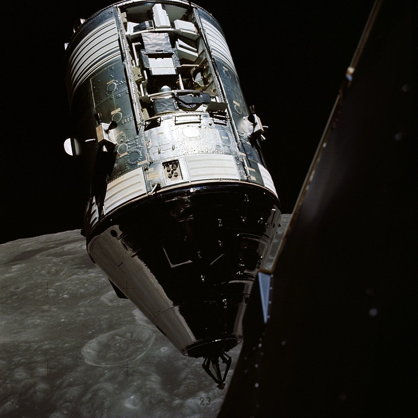
Grumman built the Apollo Lunar Module for NASA as a two-stage lander for a crew of two. The descent stage landed on the Moon and was also the launch platform for the ascent stage, which carried the two astronauts back to orbit to meet the command module. It was left behind on the Moon.
The lander was designed to work only in space, with a minimum-weight structure. Its structure weighed about one fifteenth of the fully loaded spacecraft. The lander is mostly aluminium alloy, with titanium where it gets hot. Layers of metal and plastic film wrap both stages in a shield against heat and micrometeoroids, which are tiny grains of space dust.
Application
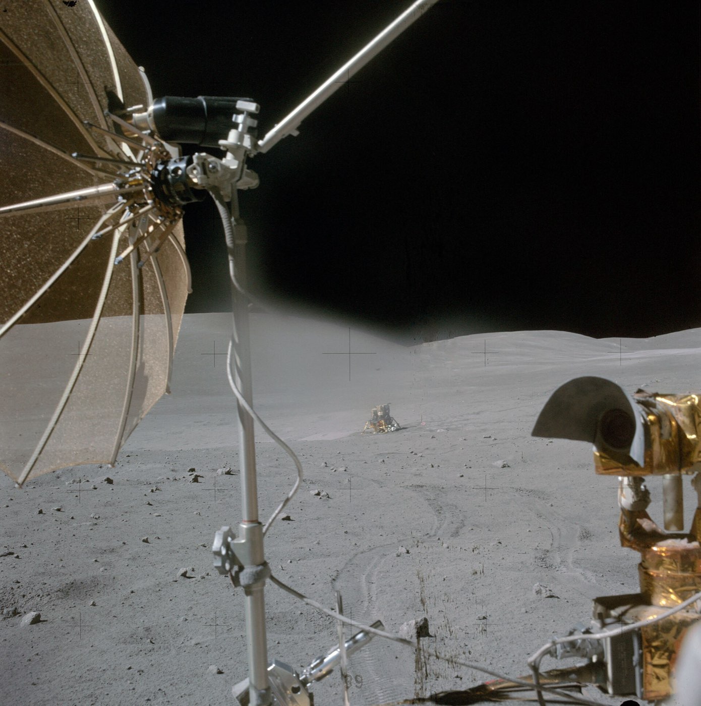
Two-stage crewed lunar lander used on Apollo missions 5 to 17 for crew landing on the Moon (four landings among the ten missions covered by the structural report). The descent stage landed and served as launch platform; the ascent stage carried two astronauts back to orbit to meet the command module.
Photos
How it is built
Ascent stage structure
The ascent stage is built mainly from aluminium alloys. The major ones are 2219 and 7075-T6, and some brackets and fasteners are titanium. The cabin is a cylindrical shell 92 inches across.
Ascent-stage cabin, midsection and aft equipment bay shell
Ascent-stage structure (major alloy)
Cabin front-face, RCS cluster trusses, decks and bulkheads
Ascent-stage brackets and fasteners
Cabin windows
The cabin windows have two panes. The outer one, made of Vycor glass, is not structural and guards against micrometeoroids and radiation. The inner one, made of tempered Chemcor glass, is the structural pane, sealed by a metallic spring inside a Teflon jacket.
Outer cabin window pane
Inner cabin window pane
Inner window seal jacket
Descent stage and landing legs
The descent stage is mostly 7075-T6 aluminium alloy, with titanium where temperatures are high. Some struts in that alloy developed stress-corrosion cracking, a slow cracking of metal under constant stress, so the heat treatment was changed to one called T73. Crushable honeycomb cartridges in the landing gear absorb the shock of touchdown.
Descent-stage main structure (beams, decks, bulkheads)
Descent-stage hot-area structure
Outrigger truss members and landing-gear struts (redesigned)
Landing-gear energy absorbers
Engine heat protection
The descent engine has its own heat protection. A base heat shield is built from alternating layers of nickel foil and a material called Fiberfrax, held on standoffs fixed to a titanium frame. A blast shield of Teflon-coated titanium sits on the upper edge of the engine compartment.
Base heat shield (BHS) insulation
Base heat shield support structure
Engine compartment blast shield
Thermal and micrometeoroid shield
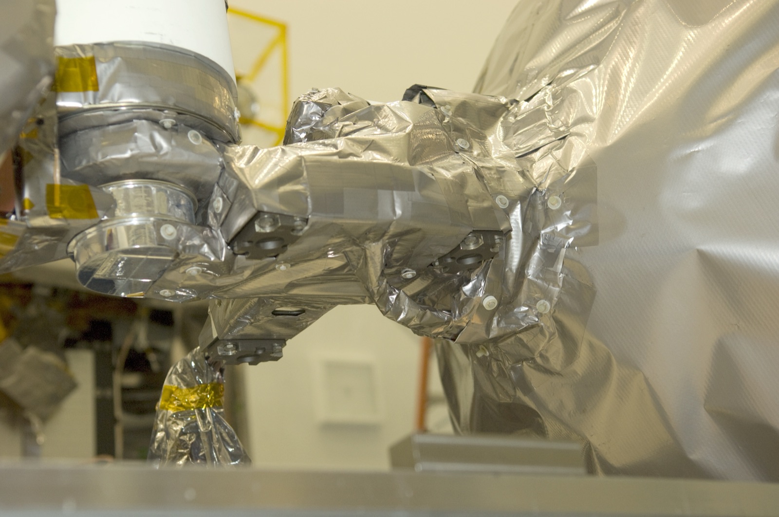
Both stages are wrapped in a thermal blanket under an outer aluminium micrometeoroid shield. The blanket's core is many layers of aluminised Mylar film, enclosed in aluminised Kapton film. Near the engine plumes, foils and mesh of Inconel and nickel replace the blanket and the aluminium skin.
Insulation blanket core
Insulation blanket inner and outer layers
Micrometeoroid shield
Plume-exposed shield areas
Where the parts areNumber of parts we have listed in each group
Ascent-stage brackets and fasteners, hot areas of the descent stage, and the frame of the base heat shield.
Inconel
Foil and mesh in the shield areas near the engine plumes, and in the thruster plume deflector.
Aluminised Mylar
The core of the thermal blanket, as thin aluminised polyester film in many layers.
Chemcor glass
The inner, structural pane of the cabin windows.
Nickel foil and Fiberfrax
Alternating layers that insulate the base heat shield, held on standoffs fixed to a titanium frame.
The materials by familyHow many of the parts that name a material use each one
Aluminium14
Titanium7
Nickel and cobalt alloys4
Glass fibre3
Other3
Polymers and foams2
Gold and silver2
How it connects to other things
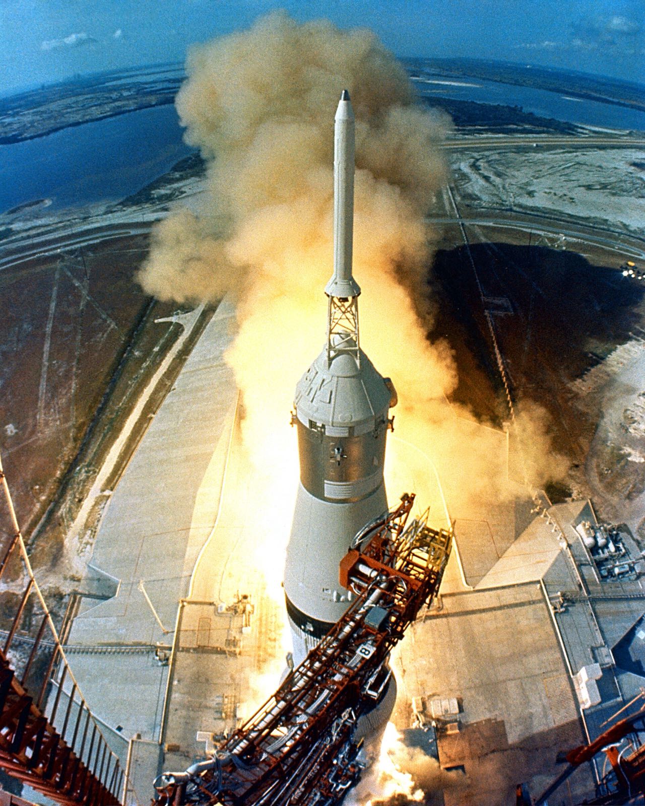
Grumman built the lander for NASA, and it was used on Apollo missions 5 to 17. The Apollo 11 lander launched on 16 July 1969 on a Saturn V from Cape Canaveral.
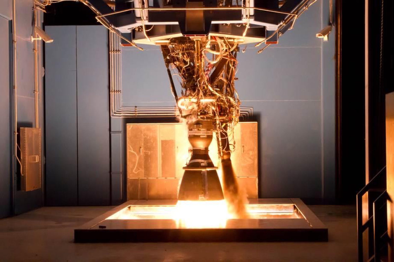
R-4D engine. Here: Reaction control thruster, Marquardt; sixteen 100 lbf thrusters in four ascent-stage clusters. There: Reaction control engine, Marquardt; sixteen ~100 lbf engines in four service module quads.
TitaniumAluminiumAluminium alloy 7075-T6Inconel foil and Inconel mesh+2 more
Where each one is used
Titanium. Here: Some brackets and fasteners (lunar module); Descent-stage hot-area structure and more. There: Outboard engine fairings and stabilization fins; Control pressure nitrogen bottle (2,200 cubic in) and more.
Aluminium. Here: Cabin front-face, RCS cluster trusses, decks and bulkheads; Micrometeoroid shield and more. There: S-IVB forward skirt, aft skirt, thrust structure and aft interstage.
Aluminium alloy 7075-T6. Here: Ascent-stage structure (major alloy); Descent-stage main structure (beams, decks, bulkheads). There: Thrust structure skin panels; Intertank and more.
Inconel foil and Inconel mesh. Here: Plume-exposed shield areas; RCS plume deflector. There: Q-ball and nose cone.
Silver-zinc plates with potassium hydroxide electrolyte. Here: Descent stage batteries (x5, silver-zinc); Ascent stage batteries (x2, silver-zinc). There: Flight batteries (x4 zinc-silver oxide); Flight batteries (x4 zinc/silver-oxide) and more.
Aluminium alloy 2219. Here: Ascent-stage cabin, midsection and aft equipment bay shell. There: LOX tank skin.
TitaniumAluminiumAluminum honeycombInconel foil and Inconel mesh+1 more
Where each one is used
Titanium. Here: Some brackets and fasteners (lunar module); Descent-stage hot-area structure and more. There: Helium tanks (2); Fuel tanks (2) and more.
Aluminium. Here: Cabin front-face, RCS cluster trusses, decks and bulkheads; Micrometeoroid shield and more. There: Radial beams; Crushable ribs (x4) and more.
Aluminum honeycomb. Here: Primary struts with crushable aluminum-honeycomb cartridge; Footpads (x4, aluminum honeycomb). There: Inner pressure shell (crew compartment); Sector and RCS exterior panels (1 in thick).
Inconel foil and Inconel mesh. Here: Plume-exposed shield areas; RCS plume deflector. There: Cryogenic oxygen tanks; Q-ball instrument package and Inconel nose cone.
Silver-zinc plates with potassium hydroxide electrolyte. Here: Descent stage batteries (x5, silver-zinc); Ascent stage batteries (x2, silver-zinc). There: Silver oxide-zinc batteries in the command module (x5).
TitaniumAluminiumSilver-zinc plates with potassium hydroxide electrolyteAluminium alloy 2219
Where each one is used
Titanium. Here: Some brackets and fasteners (lunar module); Descent-stage hot-area structure and more. There: Tread chevrons; Inner frame (MESH-1 prototype wheel; flight material not stated).
Aluminium. Here: Cabin front-face, RCS cluster trusses, decks and bulkheads; Micrometeoroid shield and more. There: Hub and wheel disc (MESH-1 prototype wheel).
Titanium. Here: Some brackets and fasteners (lunar module); Descent-stage hot-area structure and more. There: Heat shield skeleton.
Aluminium. Here: Cabin front-face, RCS cluster trusses, decks and bulkheads; Micrometeoroid shield and more. There: Pressure vessel (seven large pieces, friction-stir welded); Backbone assembly (floor structure) and more.
Titanium. Here: Some brackets and fasteners (lunar module); Descent-stage hot-area structure and more. There: Focal plane interconnecting structure; Instrument mounting feet / flexures and more.
Aluminium. Here: Cabin front-face, RCS cluster trusses, decks and bulkheads; Micrometeoroid shield and more. There: Telescope (structure and mirrors, 3 telescopes).
Aluminium alloy 7075-T6. Here: Ascent-stage structure (major alloy); Descent-stage main structure (beams, decks, bulkheads). There: Edge profiles and hot inserts.
Titanium. Here: Some brackets and fasteners (lunar module); Descent-stage hot-area structure and more. There: Propellant tanks (2); Instrument mounting flexures.
Aluminium. Here: Cabin front-face, RCS cluster trusses, decks and bulkheads; Micrometeoroid shield and more. There: Primary structure (heating/cooling panel, edge members, fittings, brackets); Optical-bench heater aluminum tape and more.
Aluminum honeycomb. Here: Primary struts with crushable aluminum-honeycomb cartridge; Footpads (x4, aluminum honeycomb). There: Iso-thermal panel with embedded heat pipes.
What we do not know
The alloys of the propellant, oxygen and helium tanks, the landing-gear honeycomb and the cabin hatch are not named, and nor are the materials of the two engines. Published layer counts for the thermal blanket differ between landers. The masses here are for the Apollo 11 lander only.
The detailed data
What is written above is built from these numbers and quotes. Each row links to the page it was taken from. Get all of it as JSON, or ask our MCP server.
Features
Designed to operate exclusively in space, with minimum-weight structure
Descent stage carries landing rocket, propellant tanks and lunar equipment; ascent stage returns crew to the command module
Enclosed in thermal and micrometeoroid shields
Stress-corrosion cracking in 7075-T6 struts led to redesign in the T73 temper
Specifications
What
Value
Total mass (Apollo 11 LM-5)
15,103 kg incl. propellants
Ascent stage dry mass
2,445 kg
Descent stage dry mass
2,034 kg incl. stowed surface equipment
Descent stage size
Octagonal prism, 4.2 m across, 1.7 m thick
Ascent stage size
About 2.8 m high, 4.0 by 4.3 m wide
Cabin diameter
92 inches
Crew compartment volume
6.65 cubic meters
Launch (Apollo 11 LM)
16 July 1969, Saturn 5, Cape Canaveral
Structural mass ratio
about 1 to 15 of structural weight to fully loaded weight
Destination
Moon surface (four landings in 10 Apollo missions)
Height with legs extended
22.92 ft
Diameter across extended landing gear
31.00 ft measured diagonally
Earth-launch mass (Apollo News Reference)
About 36,100 lb with crew and propellant
Dry mass of the whole LM
About 10,800 lb
Ascent stage propellant mass
5,200 lb
Descent stage propellant mass
19,500 lb
Ascent stage RCS propellant mass
600 lb
Habitable volume
160 cubic ft
Cabin pressure
4.8 plus or minus 0.2 psia
Crew compartment depth
Cylindrical, 92 in diameter and 42 in deep
Flight station spacing
Flight-station centerlines 44 in apart
Front window area
Each triangular front window has about 2 square ft of viewing area
Docking window area
About 80 square in
Engine count
18 engines: two large rockets (descent and ascent) plus small attitude control engines
Ascent engine thrust (NASA SP-4205)
About 15,500 N (3,500 lbf)
Ascent engine thrust (NSSDC)
About 15,000 N
Descent engine thrust (NSSDC)
About 45,000 N maximum
Apollo 11 LM lunar surface stay
21 hours 36 minutes
Lunar roving vehicle use
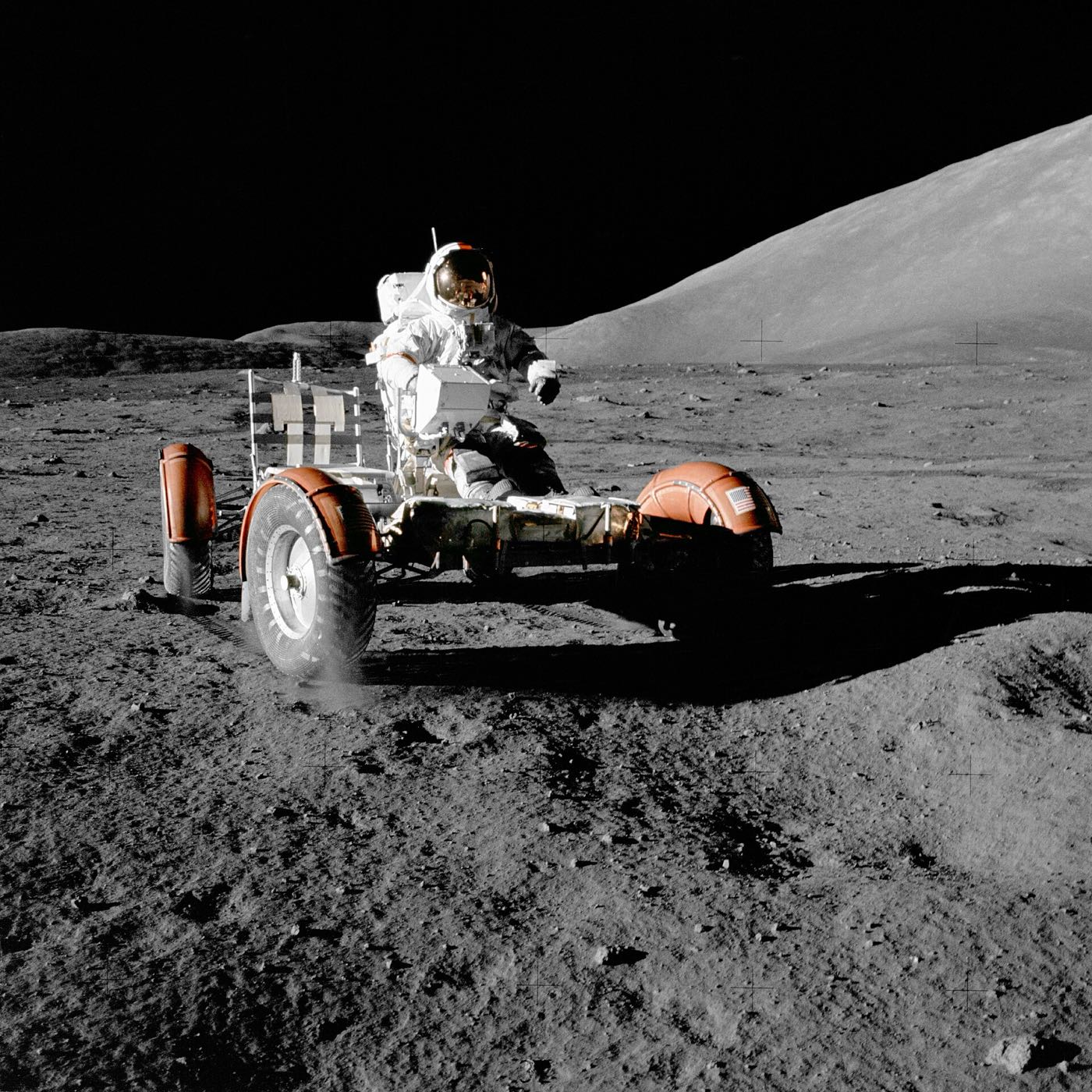
Allowed travel up to 5 km from touchdown on the later three missions
Descent propellant remaining at low-level warning
Enough for only 2 minutes of burn at hover thrust
Landing radar acquisition
Altitude data from about 38,000 ft, velocity data from about 25,000 ft
Late-mission descent engine changes
Apollo 15, 16 and 17 engines had a 10 in skirt extension and a quartz liner
Materials in detail
Each material named in the sources: where it is used here, which other products use it, and its key numbers when its material page exists.
Structural alloys, thermal shield layers and engine heat protection are stated in NASA TN D-7084 and TN D-6844. Propellant tank, ascent engine and landing-gear honeycomb materials are not stated in the sources read. Components, suppliers and links were added from public sources. A material is left blank where no source states it.
Alloys for tanks (descent and ascent propellant, oxygen, helium), landing-gear honeycomb cartridges, the cabin pressure hatch and the ascent/descent engines were not found in the sources read. 2014-series alloy was not found. The Kapton grade is given only as 'polyimide film (H-film)'. Layer counts differ between LM units and sources; the 25-layer blanket is the 'basic design' per TN D-6844. Quotes from OCR text of the NASA PDFs, with OCR spacing corrected. Mass is for Apollo 11 LM-5 only; later J-mission LMs were heavier (not checked). More detail: Not found in public sources that could be fetched: the manufacturers of the lunar module guidance computer, abort guidance system, landing radar and rendezvous radar (secondary sources name TRW for the abort guidance system and Raytheon for the computer, but no primary page with a quotable statement was reached), the S-band and VHF antenna makers, the waste-management and window-heater hardware, and the builders of the landing gear struts and footpads. Materials stated only for the parts listed: titanium propellant tanks, 6Al-4V titanium and silica-phenolic descent engine chamber, columbium C-103 nozzle, 7075-T73 gimbal frame, aluminum-honeycomb strut cartridges and footpads, aluminized Mylar helium-tank insulation, Velcro deck pile, silicone hatch seals and silver-zinc batteries; thruster body, ascent engine chamber and tank alloys are not given. Tank, hatch and radar quotes from the Grumman Apollo News Reference (LM04) and NASA SP-4205 are taken from Wayback Machine copies of hq.nasa.gov pages because the ALSJ PDFs now return 404; the enginehistory.org series (Part 9.40 to 9.46) is a secondary compilation of Grumman manuals and NASA Apollo Experience Reports that I used for most numbers. enginehistory.org lists a gross LM weight of 46,100 lb in its particulars table, which does not agree with its own stage figures or the Apollo News Reference (about 36,100 lb); only the News Reference value is given. The descent engine maximum thrust appears as 9,850 lbf (enginehistory.org), 9,870 lbf (NASA SP-4205) and 10,500 lbf at full throttle in vacuum (enginehistory.org table); all are listed. No fetched source ties the A7L suit name to the lunar module, so no relation to nasa-apollo-a7l-spacesuit is given. The Apollo 11 Press Kit and Apollo Experience Report PDFs for the LM propulsion systems were not reachable as clean text, and the web search budget ran out before NASM object pages could be checked.