About 1,522,000 lbf (uprated from 1.5 million lbf)
Chamber pressure
1,100 psi (design)
Dry mass
About 18,500 lb
Burn time
165 s per flight
Production
98 production engines
First flight
9 November 1967, Apollo 4 (AS-501), first Saturn V
In short
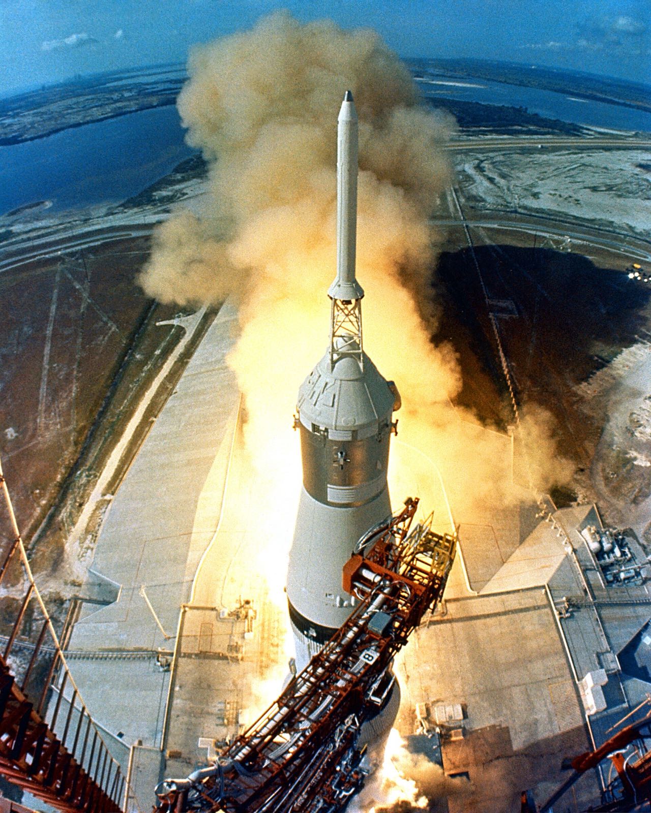
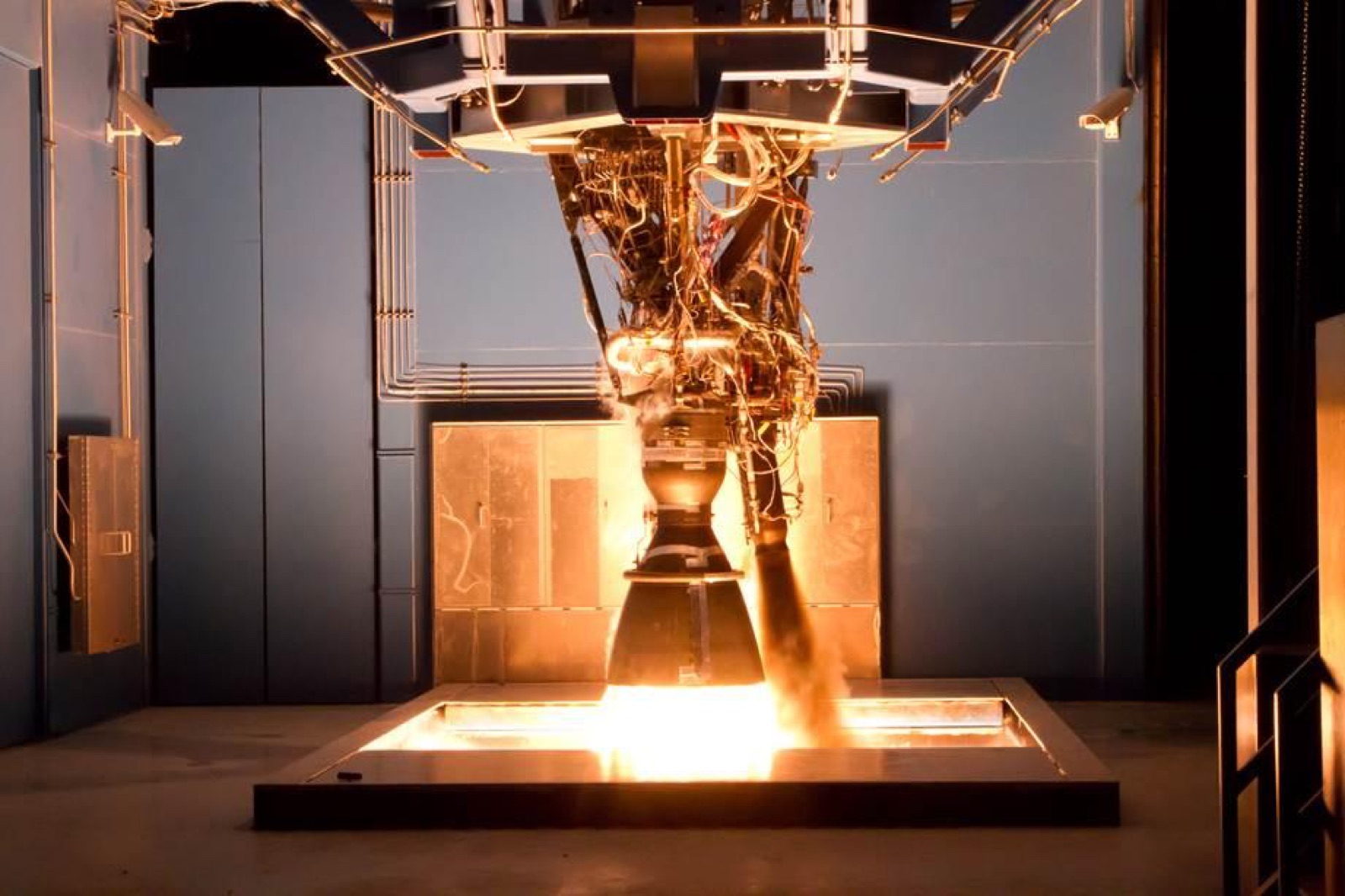
Rocketdyne, a division of North American Aviation, built the F-1 for NASA. Each engine burned RP-1 kerosene with liquid oxygen and produced about 1.5 million pounds of thrust. Five of them powered the first stage of the Saturn V, which lifted Apollo spacecraft off the pad. The first flight was the unmanned Apollo 4, on 9 November 1967.
The chamber wall is a bundle of tubes made of Inconel X-750, a nickel alloy built for high temperatures, with fuel running through them to cool the metal. The same fuel lubricates the pump bearings, so there is no separate lubrication system, and it doubles as the hydraulic fluid for the valves and steering actuators.
Application
Five F-1 engines powered the Saturn V first stage (S-IC) that lifted Apollo spacecraft off the pad, burning RP-1 and liquid oxygen. The engine is a reference case for very large kerosene engines and for nickel-superalloy tube-wall thrust chambers; NIST studied recovered hardware to see how the Inconel X-750 changed under engine heat and decades in seawater.
Photos
No photos we are allowed to show yet. If you have a photo of this product and the right to share it, send it to us.
How it is built
Chamber of brazed tubes
The chamber is a bell-shaped bundle of tubes, joined by brazing in a furnace. Brazing joins metal parts with a melted filler. Fuel flows through the tubes and cools the wall. The 178 primary tubes form the upper part, and 356 smaller secondary tubes continue below. A ring-shaped steel manifold carries the turbine exhaust.
Chamber tube bundle (178 primary and 356 secondary tubes)
Primary tubes (178)
Secondary tubes (356)
Tube-to-tube joints
Turbine exhaust manifold
Injector and baffles
The injector is a corrosion-resistant steel plate fitted with copper rings, fourteen for fuel and fifteen for oxygen, each drilled with small holes. Two circular and twelve radial baffles, cooled by fuel, split the face into thirteen compartments to keep the burn steady. Development tested 15 baffle designs and 14 injector configurations.
Injector plate (31 rings, 13 compartments)
Fuel orifice rings (14)
Oxidizer orifice rings (15)
Circular baffles (2)
Radial baffles (12)
Nozzle extension
Below the tube-walled bell, a welded double-wall skirt of nickel-base alloy extends the nozzle. Turbine exhaust gas is injected along its inner wall as a cooling film. Steel channel bands are welded around the outside to stiffen it, and asbestos blankets insulate the exit end.
Nozzle extension inner and outer walls
Reinforcing channel bands
Exit-end insulation blankets
Turbopump and gas generator
One shaft carries the oxygen pump at the top, the fuel pump below it and the turbine beneath that. Hot gas from a gas generator drives the turbine. Its welded housing is René 41, a high-nickel alloy. Cracks appeared in development and were traced to an improper welding process.
One oxygen valve and one fuel valve sit on each side of the engine, sealed with machined Teflon. A cartridge of self-igniting fluid, 85 percent triethylborane and 15 percent triethylaluminium, starts the engine without a pyrotechnic igniter. A spherical steel joint lets the four outer engines swivel.
Main oxidizer valves (2)
Main fuel valves (2)
Hypergolic igniter fluid
Gimbal bearing
Gimbal socket liner
Where the parts areNumber of parts we have listed in each group
Turbopump10
Thrust chamber8
Injector5
Valves and ducts5
Gimbal and thermal protection5
Gas generator and heat exchanger4
Nozzle extension3
Oxidizer dome and manifold2
Propellants2
Ignition1
What it is made of
Inconel X-750
The bundle of chamber tubes. NIST examined recovered chambers and found that engine heat had changed the metal's internal structure.
The injector's fuel and oxygen orifice rings, and its fuel-cooled circular and radial baffles.
René 41
The turbine housing. Cracks in it were traced to an improper welding process during development.
Nickel-base alloy (grade not stated)
Inner and outer walls of the nozzle extension, and part of the welded oxygen dome.
Corrosion-resistant steel
The injector plate, the turbine exhaust manifold, the nozzle's reinforcing bands and part of the oxygen dome.
Asbestos
Blankets on the exit end of the nozzle extension, and layered insulators reinforced with Inconel wire.
The materials by familyHow many of the parts that name a material use each one
Nickel and cobalt alloys9
Other7
Stainless steel6
Copper4
Polymers and foams3
Aluminium2
Glass fibre2
How it connects to other things
Five F-1 engines sat at the base of the Saturn V first stage, called the S-IC. The four outer engines swivelled to steer the rocket, and the centre engine stayed fixed. Rocketdyne built all 98 production engines, and 70 of them were tested in S-ICs. The F-1 followed Rocketdyne's earlier S-3D and H-1 engines in its propellants, packaging, chamber design and start sequence.
Copper. Here: Fuel orifice rings (14); Oxidizer orifice rings (15) and more. There: Helical antenna (+Z end card); Outer copper foil and more.
Aluminium. Here: High-pressure propellant ducts. There: Backplane grounding to frame.
What we do not know
The published description names many materials but few grades. The corrosion-resistant steel and the nickel-base alloy have none, and the pump impellers, pump housings, braze and valve bodies are not described at all. Sources also disagree on size: 16 feet long in one, 18 feet tall in another.
The detailed data
What is written above is built from these numbers and quotes. Each row links to the page it was taken from. Get all of it as JSON, or ask our MCP server.
Features
One turbopump on one shaft drives both the LOX and fuel pumps
RP-1 fuel lubricates the turbopump bearings, so no separate lubrication system
Fuel also acts as the hydraulic fluid for the engine valves and thrust-vector actuators
Turbine exhaust gas film-cools the inner wall of the welded nozzle extension
Hypergolic cartridge starts the engine without a pyrotechnic igniter
Injector baffles divide the face into thirteen compartments to damp combustion instability
Development tested 15 baffle designs and 14 injector configurations
Tank-head start takes about five seconds with no outside help
Ground crews fill the chamber tubes with ethylene glycol about 15 hours before launch
Turbine housing alloy Rene 41 cracked in development until the welding process was fixed
NIST found engine heat had changed the Inconel X-750 microstructure of recovered chambers
Specifications
What
Value
Sea-level thrust
About 1,522,000 lbf (uprated from 1.5 million lbf)
Original thrust rating
1.5 million lbf per engine
Specific impulse
265 s
Chamber pressure
1,100 psi (design)
Propellants
Liquid oxygen and RP-1 kerosene
Cycle
Gas generator
Nozzle area ratio
16:1 (tube wall to 10:1, double-wall extension to 16:1)
Dry mass
About 18,500 lb
Envelope (EngineHistory.org)
12 ft diameter by 16 ft long
Envelope (Biggs, Rocketdyne)
18 ft tall, 12 ft wide
Burn time
165 s per flight
Qualification life
20 starts and 2,250 s
Turbopump layout
One shaft: LOX pump, fuel pump, turbine
Engines per vehicle
5 on the Saturn V S-IC first stage (4 outer engines gimbaled, centre engine fixed)
Production
98 production engines
Contract
NASA contract NAS8-18734 for 30 F-1 engines (approved 18 Nov 1966)
First flight
9 November 1967, Apollo 4 (AS-501), first Saturn V
First flight date
1967-11-09
Materials in detail
Each material named in the sources: where it is used here, which other products use it, and its key numbers when its material page exists.
triethylborane 85% and triethylaluminum 15% pyrophoric fluid
triethylborane-triethylaluminum
Used in 1 partHypergolic igniter fluid
Material page coming soon
Viton-A
viton-a
Used in 1 partDome-to-injector outer O-ring
Material page coming soon
Every part we have
Part lists and materials come from the Rocketdyne-derived F-1 description (EngineHistory.org Part 8.12), its history page (Part 8.11), NASA SP-2009-4545 and NIST. Chamber tubes, injector, dome, nozzle extension, seals, gimbal, ducts and insulation have a stated material; turbopump rotors, pump housings (except the Rene 41 turbine housing), braze alloys and valve bodies do not.