Two 2S1P Li-ion 18650 packs on one card, 7.2 V at 5.2 Ah
Data bus
1 Mbps CAN
In short
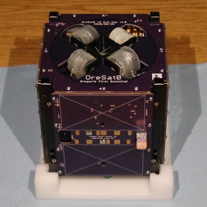
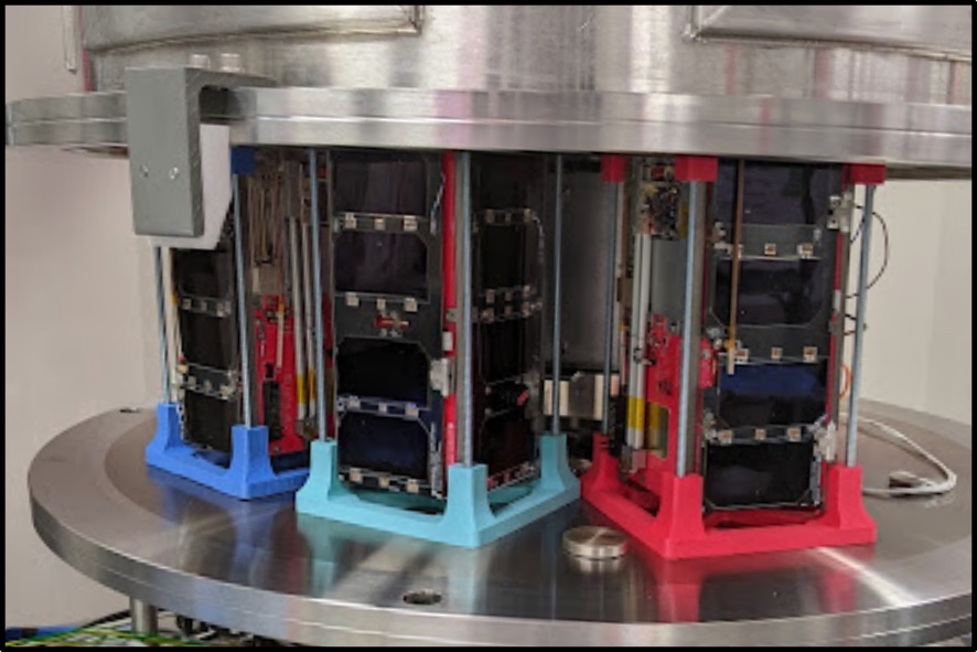
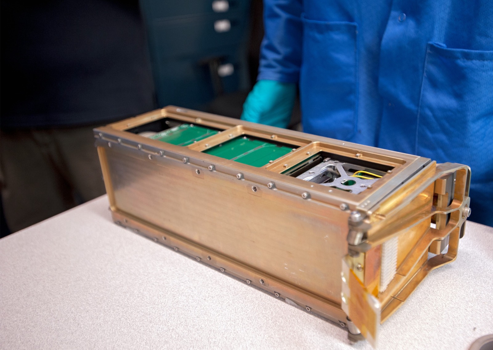
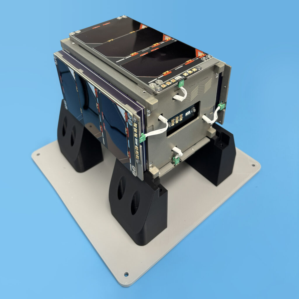
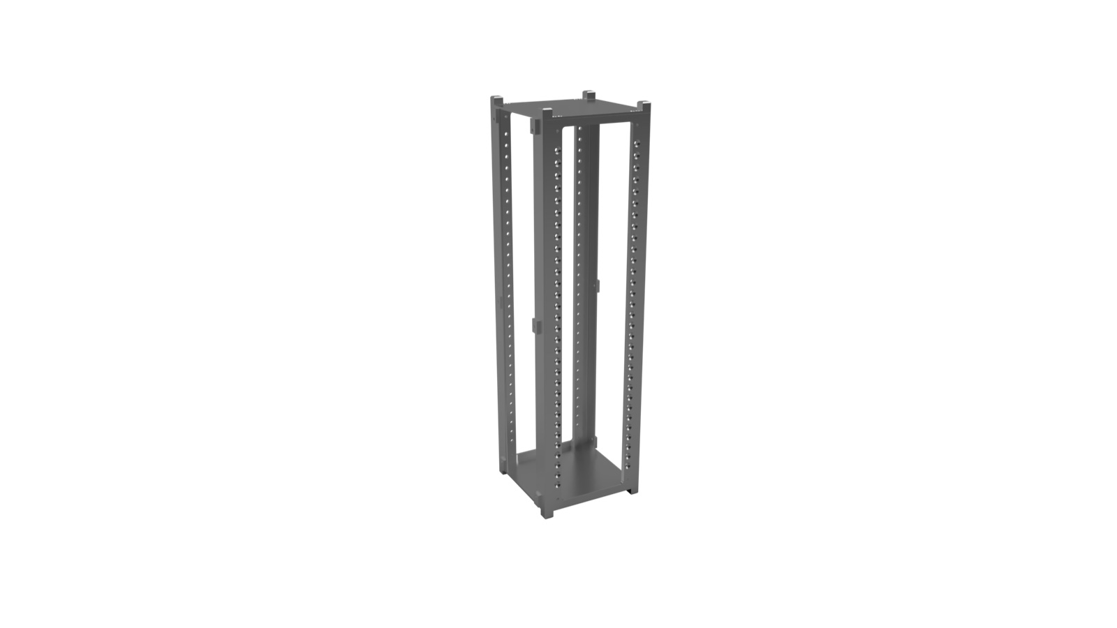
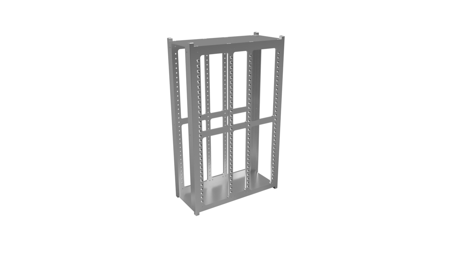
OreSat is a CubeSat design from PSAS and Oregon State that scales from 1U to 3U. Its structure, electronics and software are public on GitHub, so anyone can read how a small satellite is put together. Each subsystem is one or more circuit cards, held in an aluminium frame like cards in a cage.
Students can machine the frames themselves on a three-axis mill, from 15 mm plate of 6061-T6 aluminium. The frames are anodised black, which grows an oxide layer on the metal. That layer passes heat between cards and frame but not electricity. The team has flown its gallium arsenide solar design and is working on a silicon one.
Application
An open-source CubeSat bus whose structure, electronics and software are public on GitHub. Anyone can read how a real small satellite is built, down to the frame alloy, circuit-board stack and solar modules, which makes it a useful reference for teams and students.
Photos
How it is built
Frame and clamps
The frames and the wedge clamps that hold each card are both 6061-T6 aluminium, anodised black. Where an antenna card must be grounded to the frame, the anodising is masked off and Alodine 1201 coating goes on instead. The structure is held together with stainless steel 18-8 Torx screws, sizes M2 and M2.5.
1U +X frame
Card wedge (card clamp)
Electrical-ground contact patches on frames
Structure fasteners (programme standard)
The backplane
The backplane is the circuit board that the cards connect to. It carries a 1 Mbps CAN data bus and radio connectors. A ring of bare copper on its back touches the anodised frame to pass heat. Shoulder bolts hold it loosely enough to flex, because aluminium and circuit board expand by different amounts.
Back-side thermal ring
Backplane locating shoulder bolt
Backplane grounding to frame
Circuit boards
The main circuit boards have four layers and are 1.59 mm thick. Several call for Isola FR408HR laminate or an equivalent. The assembly notes insist on leaded solder paste for most cards, and the boards get no conformal coating, a protective film over the circuits.
PCB laminate core
PCB laminate prepreg
Outer copper foil
Solder paste
Conformal coating
Solar modules
Each 1U carries four solar modules, one per side face. A module has two Spectrolab XTE-SF cells and peaks at 2.34 W. Cells are placed by hand and stuck down with pressure-sensitive adhesive. Each module has its own maximum power point tracker, a circuit that keeps the cells at their best operating point.
Solar cell (SpectraLabs XTE-SF, 2 per module)
Solar cell attachment
Battery card
The battery card holds four Tenergy 18650 lithium-ion cells in a 3D-printed nylon holder, wired as two packs for 7.2 V at 5.2 Ah. Polyimide heater tapes keep the cells above 0 °C. Hardware circuits guard against overcharge, overdischarge and overcurrent, and the card has inhibit and shutdown switches.
18650 cell (Tenergy, 4 per card)
Cell holder
Polyimide thermofoil heater (Minco, 2 per card)
Switch (battery inhibit and shutdown, Aratas/Omron D2F)
Where the parts areNumber of parts we have listed in each group
C3 card: electronic components (25 most significant of the BOM)25
Solar module: electronic components (25 most significant of the schematic)25
Battery card: electronic components (25 most significant of the schematic)25
Battery card: cells, holder, heaters, PCB and assembly materials16
Solar module (1U GaAs + MCXN): cells, PCB and assembly materials12
Frame, card clamps and mechanical parts11
C3 card: PCB laminate, finish and assembly materials11
Fasteners and COTS mechanical hardware10
Backplane: PCB laminate, finish and assembly materials10
End card and end cap (OreSat1 +Z): PCB and assembly materials9
The cells in the solar modules, two Spectrolab XTE-SF cells per module.
Lithium-ion cells
Four 18650 cells on the battery card.
Isola FR408HR
Circuit-board laminate on several cards, including the backplane.
The materials by familyHow many of the parts that name a material use each one
Other41
Aluminium9
Copper9
Gold and silver6
Polyimide2
Polymers and foams1
How it connects to other things
PSAS and Oregon State keep OreSat's structure, electronics and software in separate GitHub repositories. The solar hardware is licensed as open hardware under CERN-OHL-S v2. Chip resistors come from Stackpole Electronics and ceramic capacitors from Murata Electronics. One flight unit, OreSat0, has an end cap marked Oregon's First Satellite.
Lithium-Ion. Here: 18650 cell (Tenergy, 4 per card); Battery cell model (README). There: Puffin battery pack (Puffin Pack); Draft power module cells (Li-ion or LiFePO4).
Gallium arsenide. Here: Solar cell (SpectraLabs XTE-SF, 2 per module); Solar cell technology. There: Draft solar panel cells (triple-junction GaAs).
What we do not know
The team has not published a total mass for the satellite. The drawings call for Type II anodising but cite no specification, the solder paste is only called leaded, and the laminate for the solar and battery cards is left unspecified.
The detailed data
What is written above is built from these numbers and quotes. Each row links to the page it was taken from. Get all of it as JSON, or ask our MCP server.
Features
Card-cage bus: one or more cards per subsystem
Each solar module has its own true MPPT
Solar modules thermally connected to the frame
Backplane uses CAN, SMPM RF connectors and microstrips
Hardware overcharge, overdischarge and overcurrent protection on battery card
Battery card has inhibit switches and shutdown switches
Type II anodization gives thermal but not electrical contact between cards and structure
Backplane flexure allowed for thermal expansion mismatch via shoulder bolts
Deployable tri-band 4-element turnstile antenna
Frames machinable by students; 1U kit cost
Specifications
What
Value
Scalable size
1U to 3U
Frame material
6061-T6 aluminium, Type II anodized (black)
Frame stock
15 mm plate, machinable on a 3-axis mill
Structure fasteners
Torx button head, stainless 18-8, M2 and M2.5
Solar modules per U
1 per X,Y side (4 per U)
Solar module cells and power
2 Spectrolab XTE-SF cells, 2.34 Wpk per module
Solar module PCB size
83.0 x 100.0 mm, 4 layer, 1.59 mm (GaAs + MCXN variant)
Solar module boost voltage
up to 8.2 V
Battery pack
Two 2S1P Li-ion 18650 packs on one card, 7.2 V at 5.2 Ah
Cell model
Tenergy 30005-0 (ICR 18650-2600), 2600 mAh
Bus voltage
6.0 V min, 7.2 V typical, 8.4 V max (2S Li-ion)
Data bus
1 Mbps CAN
PCB thickness
1.59 mm (0.063 in)
PCB stackup (4 layer)
1 oz outer Cu, 0.5 oz inner Cu, Isola FR408HR core 0.991 mm, prepreg 0.200 mm
Structure card fasteners (backplane)
M2 x 0.4 x 4 mm
Repository licence
CERN-OHL-S v2 (solar hardware repo)
Materials in detail
Each material named in the sources: where it is used here, which other products use it, and its key numbers when its material page exists.
Used in 1 partStructure fasteners (programme standard)
Material page coming soon
urethane PSA
urethane-psa
Used in 1 partHeater attachment adhesive
Material page coming soon
Every part we have
Parts-level for frame, PCB materials, connectors, solar cells, battery cells and heaters from public repos and slides, but electronic-component assemblies are capped at the 25 most significant lines each and the frame fastener materials are not stated.
Type II anodize (no specification number given) · Black anodize on all aluminium frame and card-clamp parts
What the sources leave out
Fastener materials of the McMaster-Carr part numbers (90910A920, 92703A159, 92290A060, 91630A221, 93600A061, 84985A46, 90263A111) are not stated in the BOM; the slides only say the standard is SS 18-8 Torx button head M2/M2.5. Type II anodize has no specification number on the drawings. Solder alloy is only 'leaded' (no alloy, no flux product). Solar-module and battery-card PCB laminate is unspecified ('no requirements on the prepreg or core'). Solar cell attachment adhesive (PSA) product, cell coverglass and interconnect materials sit in a Google Docs SOP not read here. Battery pack tabs/wiring, thermal pads and the inhibit-switch plunger fasteners are not listed. The battery README names Tenergy 30005-0 while the schematic part is MH48285, a discrepancy the repo does not explain. Full PCBA BOM CSV and the Google Sheets BOM links in the battery README were not readable (no CSV in the repos); component lines were taken from KiCad schematic fields (MFR/MPN/Description), so DNP lines are excluded and some MPN fields are mis-filled in the source (TPS63060DSCR, LT1618EMSTRPBF, where the part number sits in Value). Electronic assemblies are capped at 25 lines, so many resistors/capacitors/ICs of C3 (111 distinct lines), solar module (about 50) and battery card (about 70) are not listed. ADCS, GPS, star tracker, DxWiFi, camera and antenna-card BOMs, the 3U/ESI frames, the OnShape CAD (current structure CAD) and the 9 GB structure repo's SolidWorks files were not read.