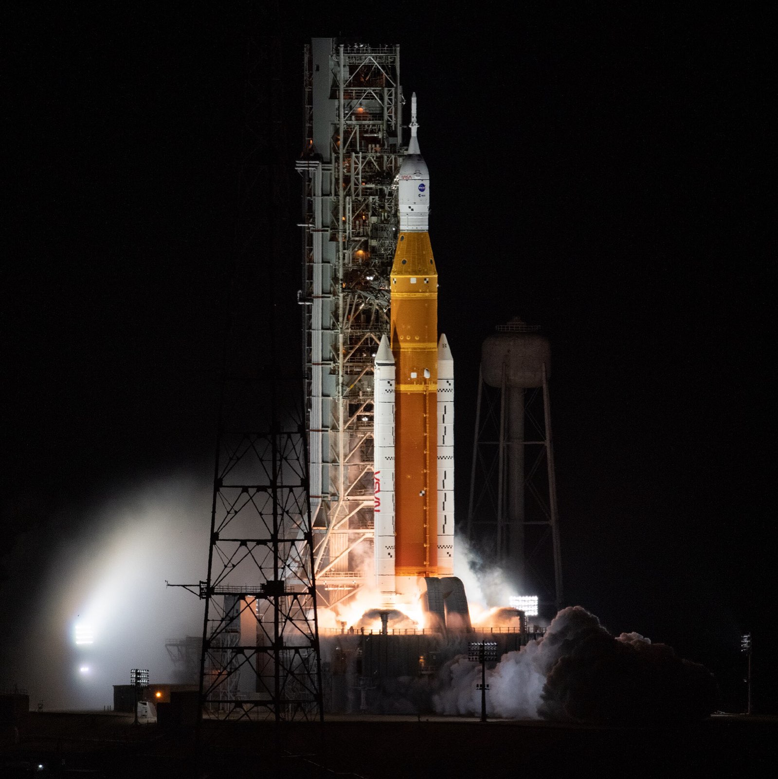
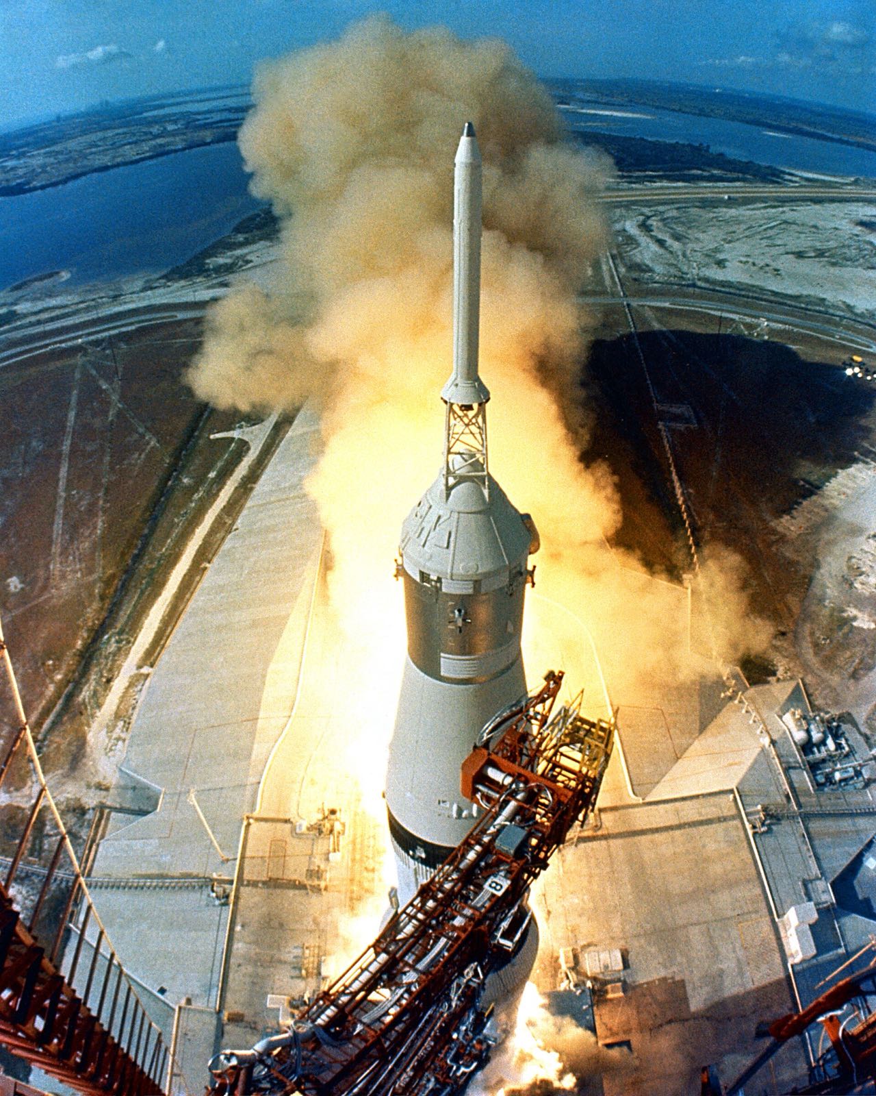
Saturn V with Apollo 11 lifting off, seen from the launch tower looking down
NASA

Saturn V

Saturn V is the three-stage NASA rocket that sent Apollo crews to the Moon.

Launch vehicles
Product IDnasa-saturn-v
Height
363 ft (111 m)
Liftoff thrust
7.6 million lb (34.5 million N)
Payload to Earth orbit
about 118,000 kg (130 tons)
First stage size
33 ft diameter, 138 ft high
Launches
13 Saturn V launches, 10 crewed
Thrust-producing devices
91 (engines, solid motors and thrusters)

In short

Saturn V was the three-stage rocket NASA used to send crews to the Moon. It stood 363 feet tall and weighed about 6.2 million pounds at liftoff, with 7.6 million pounds of thrust. Thirteen were launched, ten with crews. The first flew in 1967, on the uncrewed Apollo 4.

Its stages were welded and riveted from aluminium alloys, chosen for strength at cryogenic, or extremely low, temperatures. Honeycomb sandwich panels gave insulation and structure. The whole stack was designed with 91 thrust-producing devices: engines, solid motors and small thrusters.

Application

The Apollo-era three-stage rocket that sent crews to the Moon. Its stage structures were welded and riveted aluminium alloys chosen for strength at cryogenic temperatures, with honeycomb sandwich panels for insulation and structure.

How it is built

First stage, S-IC

The S-IC is 33 feet across and 138 feet tall, with a kerosene tank below an oxygen tank. Both have 2219 aluminium skins. Five insulated tunnels carry oxygen down through the kerosene tank to the five F-1 engines at the base.

  • Fuel tank barrel skin
  • LOX tank skin
  • RP-1 fuel tank
  • LOX suction lines (x5, 17 in) in insulated tunnels
  • F-1 engines (x5: four gimbaled outer, one fixed centre)

Second stage, S-II

The S-II is 81.5 feet long and 33 feet across, and most of it is welded 2014-T6 aluminium. The wall shared by its two tanks is a bonded sandwich of aluminium sheets around a fibreglass and phenolic honeycomb core. Foam-filled honeycomb insulates the hydrogen tank.

  • Main structure and tanks
  • Common bulkhead facing sheets
  • Common bulkhead core
  • LH2 tank external insulation
  • J-2 engines (x5: four gimbaled outer, one fixed centre)

Third stage, S-IVB

The S-IVB tanks are waffle-milled 2014 aluminium alloy. Blocks of sealed fibreglass and polyurethane insulation are bonded into the recesses of the waffle pattern on the hydrogen tank. One J-2 engine burns twice, first to reach Earth orbit and again for the trip to the Moon.

  • Propellant tanks
  • Common bulkhead domes
  • LH2 tank insulation
  • J-2 engine (x1, restartable)

Instrument Unit

The Instrument Unit is a ring 260 inches across and 36 inches tall, weighing about 4,400 pounds. Its structure is aluminium honeycomb sandwich with extruded aluminium channels, in three 120 degree segments. IBM built it, and its launch vehicle digital computer solved the guidance equations.

  • IU ring structure
  • Launch vehicle digital computer (LVDC)
  • ST-124-M3 inertial platform
  • Thermal conditioning system (TCS) with sublimator and cold plates

Launch escape system

A launch escape tower topped the stack. It was a welded titanium tubing truss about 10 feet long, and it carried motors that could pull the command module away in an abort. A boost protective cover of fibreglass and cork shielded the capsule from motor exhaust and ascent heating.

  • Launch escape tower
  • Launch escape motor
  • Tower jettison motor (TE-M-380)
  • Boost protective cover
Where the parts areNumber of parts we have listed in each group
  • S-IC first stage (Boeing)17
  • S-II second stage (North American Aviation)14
  • S-IVB third stage (Douglas Aircraft)13
  • Instrument Unit (IBM)9
  • S-IC first stage6
  • Launch escape system (top of the stack)6
  • S-II second stage5
  • S-IVB third stage4
  • Instrument Unit1

What it is made of

  • Aluminium alloy 2219

    The skins of the first stage's fuel and oxygen tanks.

  • Aluminium alloy 2014-T6

    Most of the second stage, including its tanks, and the domes of the third stage's shared bulkhead.

  • Aluminium alloy 7075

    Corrugated skin panels of the first stage's thrust structure, intertank and forward skirt, and the shells of the second stage's skirts.

  • 16-7 PH stainless steel honeycomb

    The heat shield of the first stage's thrust structure, brazed to thin steel face sheets.

  • Fibreglass and polyurethane insulation

    Sealed blocks bonded into the waffle pattern of the third stage's hydrogen tank.

  • Titanium

    The first stage's engine fairing bottoms and fins, the launch escape tower and some gas bottles.

The materials by familyHow many of the parts that name a material use each one
  • Aluminium14
  • Glass fibre5
  • Stainless steel3
  • Titanium3
  • Gold and silver3
  • Polymers and foams1
  • Nickel and cobalt alloys1

How it connects to other things

Five F-1 engines powered the first stage and five J-2 engines the second. One J-2 drove the third stage, which also flew as the second stage of the Saturn IB. Rocketdyne built both engines. Boeing made the first stage, North American Aviation the second, Douglas Aircraft the third and IBM the Instrument Unit. The Apollo command and service modules rode on top, with the lunar module inside an adapter. The last Saturn V launched Skylab.

Engines

  • F-1 engine

    Rocketdyne, Division of North American Aviation

    S-IC: five engines, RP-1 and LOX

  • J-2 engine

    Rocketdyne

    S-II: five single-start engines

    1 more detail

    S-IVB: one engine

Carries

Launches

Builds on

  • Saturn IB

    The S-IVB stage also flew as the second stage of the Saturn IB

Made or supplied by

  • Boeing

    Built the S-IC first stage at Michoud

  • North American Aviation

    Built the S-II second stage

  • Douglas Aircraft

    Built the S-IVB third stage

  • IBM (International Business Machines)

    Built the Instrument Unit

  • Rocketdyne

    Developed the F-1 engine for the S-IC

    1 more detail

    Won the J-2 engine contract

  • Thiokol

    S-IC retro rocket motors

  • Moog, Inc.

    One of two vendors of S-IC thrust vector control servoactuators

  • TRW

    S-IVB APS attitude control engines

  • Lockheed Propulsion Co.

    Launch escape motor

  • Hercules, Inc.

    Later builder of the S-II RS-U-601 ullage motors

Products that use the same materials

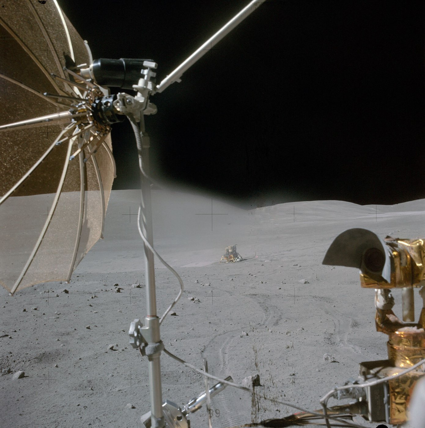
  • Apollo Lunar Module (LM)

    Grumman / NASA

    Aluminium alloy 7075-T6Titaniumzinc-silver oxide batteries2219 aluminium alloy+2 more
    Where each one is used

    Aluminium alloy 7075-T6. Here: Thrust structure skin panels; Intertank and more. There: Ascent-stage structure (major alloy); Descent-stage main structure (beams, decks, bulkheads).

    Titanium. Here: Outboard engine fairings and stabilization fins; Control pressure nitrogen bottle (2,200 cubic in) and more. There: Some brackets and fasteners (lunar module); Descent-stage hot-area structure and more.

    zinc-silver oxide batteries. Here: Flight batteries (x4 zinc-silver oxide); Flight batteries (x4 zinc/silver-oxide) and more. There: Descent stage batteries (x5, silver-zinc); Ascent stage batteries (x2, silver-zinc).

    2219 aluminium alloy. Here: LOX tank skin. There: Ascent-stage cabin, midsection and aft equipment bay shell.

    Aluminium. Here: S-IVB forward skirt, aft skirt, thrust structure and aft interstage. There: Cabin front-face, RCS cluster trusses, decks and bulkheads; Micrometeoroid shield and more.

    Inconel. Here: Q-ball and nose cone. There: Plume-exposed shield areas; RCS plume deflector.

  • Apollo Command and Service Module

    North American Aviation

    Titaniumzinc-silver oxide batteriesAluminiumfiberglass honeycomb+2 more
    Where each one is used

    Titanium. Here: Outboard engine fairings and stabilization fins; Control pressure nitrogen bottle (2,200 cubic in) and more. There: Helium tanks (2); Fuel tanks (2) and more.

    zinc-silver oxide batteries. Here: Flight batteries (x4 zinc-silver oxide); Flight batteries (x4 zinc/silver-oxide) and more. There: Silver oxide-zinc batteries in the command module (x5).

    Aluminium. Here: S-IVB forward skirt, aft skirt, thrust structure and aft interstage. There: Radial beams; Crushable ribs (x4) and more.

    fiberglass honeycomb. Here: Thrust structure heat shield. There: Boost protective cover.

    impregnated fiberglass, honeycomb-cored laminated fiberglass and cork. Here: Boost protective cover. There: Thruster outer wrap.

    Inconel. Here: Q-ball and nose cone. There: Cryogenic oxygen tanks; Q-ball instrument package and Inconel nose cone.

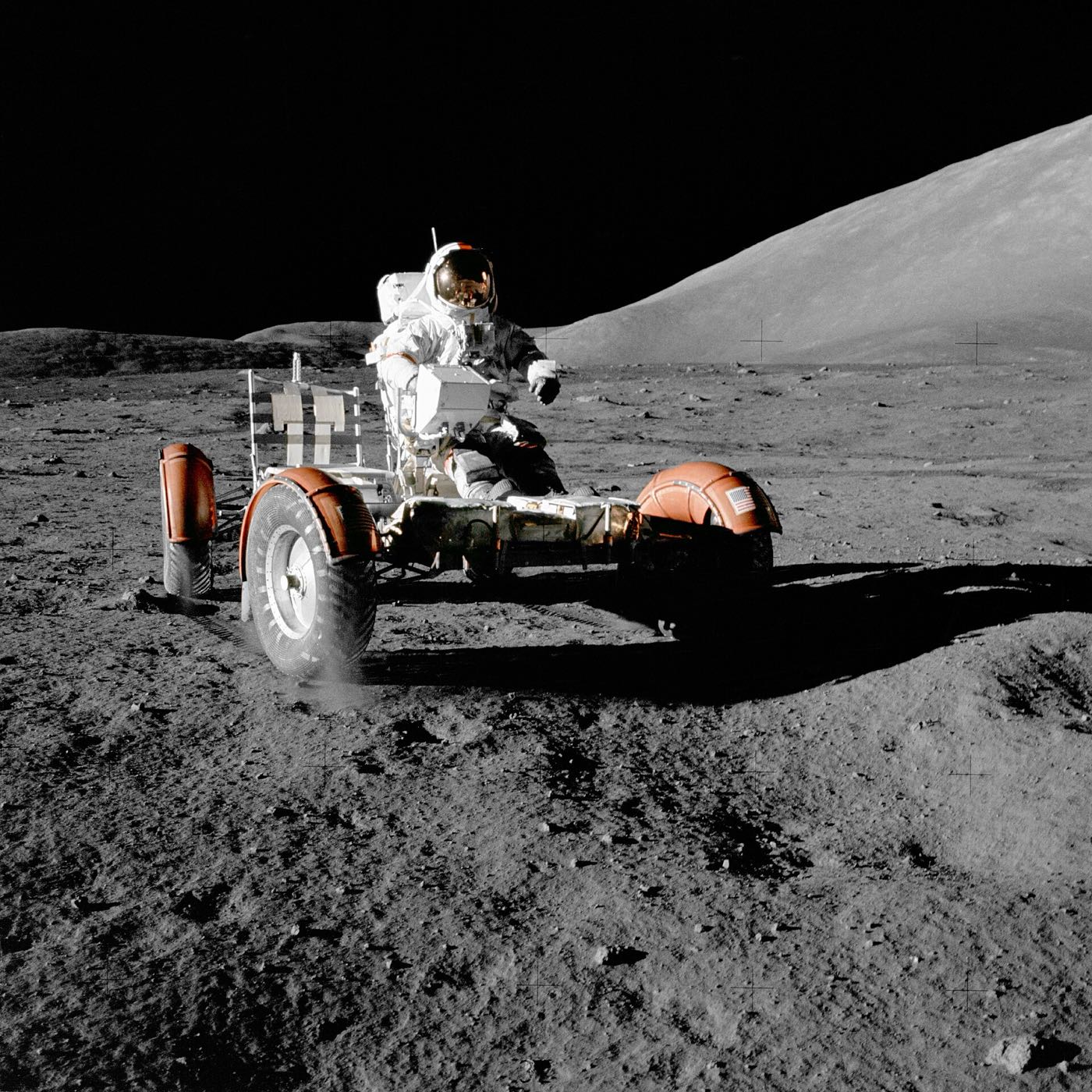
  • Apollo Lunar Roving Vehicle

    Boeing

    Titaniumzinc-silver oxide batteries2219 aluminium alloyAluminium+1 more
    Where each one is used

    Titanium. Here: Outboard engine fairings and stabilization fins; Control pressure nitrogen bottle (2,200 cubic in) and more. There: Tread chevrons; Inner frame (MESH-1 prototype wheel; flight material not stated).

    zinc-silver oxide batteries. Here: Flight batteries (x4 zinc-silver oxide); Flight batteries (x4 zinc/silver-oxide) and more. There: Batteries (2).

    2219 aluminium alloy. Here: LOX tank skin. There: Frame.

    Aluminium. Here: S-IVB forward skirt, aft skirt, thrust structure and aft interstage. There: Hub and wheel disc (MESH-1 prototype wheel).

    impregnated fiberglass, honeycomb-cored laminated fiberglass and cork. Here: Boost protective cover. There: Fenders.

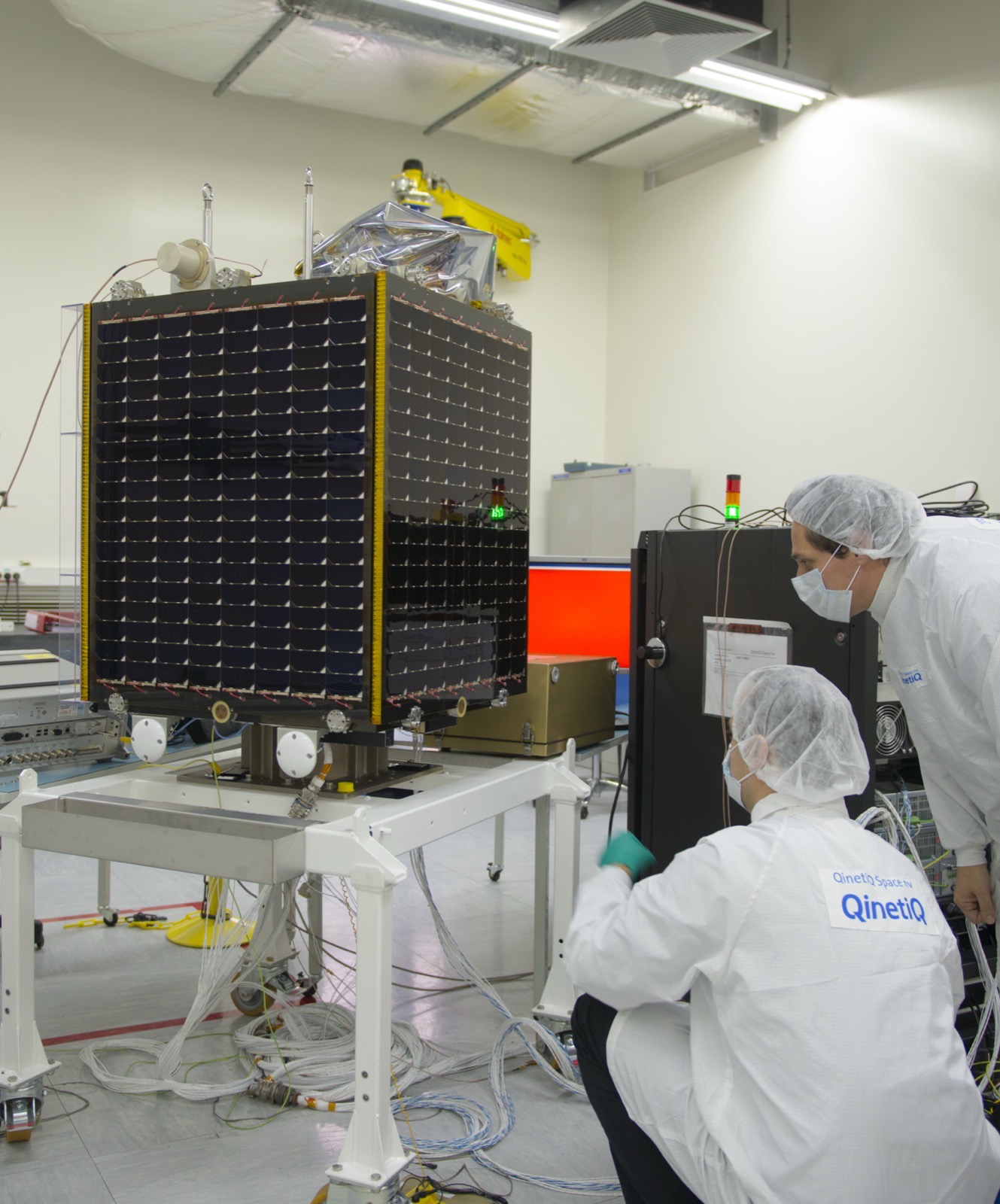
  • Proba-V

    ESA

    Aluminium alloy 7075-T6TitaniumAluminiumAluminium honeycomb core
    Where each one is used

    Aluminium alloy 7075-T6. Here: Thrust structure skin panels; Intertank and more. There: Edge profiles and hot inserts.

    Titanium. Here: Outboard engine fairings and stabilization fins; Control pressure nitrogen bottle (2,200 cubic in) and more. There: Focal plane interconnecting structure; Instrument mounting feet / flexures and more.

    Aluminium. Here: S-IVB forward skirt, aft skirt, thrust structure and aft interstage. There: Telescope (structure and mirrors, 3 telescopes).

    Aluminium honeycomb core. Here: IU ring structure. There: Structure (summary).

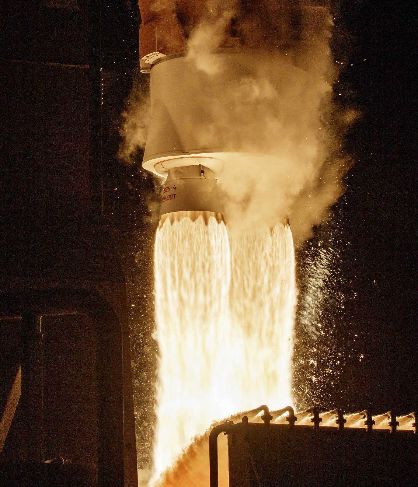
  • Atlas V

    United Launch Alliance

    Aluminium alloy 7075-T62014 aluminium alloyAluminiumAluminium honeycomb core
    Where each one is used

    Aluminium alloy 7075-T6. Here: Thrust structure skin panels; Intertank and more. There: Aft transition structure ring frames and skins.

    2014 aluminium alloy. Here: Common bulkhead facing sheets; Propellant tanks. There: Forward adapter skirt and RP adapter skirt.

    Aluminium. Here: S-IVB forward skirt, aft skirt, thrust structure and aft interstage. There: Booster LO2 and RP tanks; Propellant feedlines and more.

    Aluminium honeycomb core. Here: IU ring structure. There: Booster heat shield; 5-m payload fairing and more.

  • Rockwest solar array substrate

    Rockwest Composites

    AluminiumAluminium honeycomb coreimpregnated fiberglass, honeycomb-cored laminated fiberglass and cork
    Where each one is used

    Aluminium. Here: S-IVB forward skirt, aft skirt, thrust structure and aft interstage. There: Aluminium inserts, in-plane and out-of-plane (DiskSat build).

    Aluminium honeycomb core. Here: IU ring structure. There: Core.

    impregnated fiberglass, honeycomb-cored laminated fiberglass and cork. Here: Boost protective cover. There: G10 fiberglass skins with integrated copper traces.

What we do not know

The published accounts do not say which alloys went into the F-1 and J-2 engines, or what insulated the first-stage tanks. They also leave out the fasteners, the welding filler and most of the Apollo spacecraft's materials, and they name few makers of valves, pumps and batteries.

The detailed data

What is written above is built from these numbers and quotes. Each row links to the page it was taken from. Get all of it as JSON, or ask our MCP server.

Features

  • First stage burns five F-1 engines on RP-1 and LOX
  • Second stage uses five J-2 engines

Specifications

WhatValue
Height363 ft (111 m)
Liftoff thrust7.6 million lb (34.5 million N)
Payload to Earth orbitabout 118,000 kg (130 tons)
First launch1967 (Apollo 4, uncrewed)
S-IC size33 ft diameter, 138 ft high
S-IC empty mass303,000 lb
S-IVB dry massabout 33,142 lb including interstage
S-IVB LH2 tank size21.75 ft diameter, 40 ft long
S-II size and mass81.5 ft long, 33 ft diameter, about 88,400 lb empty (98,659 lb with interstage), about 1,034,900 lb fuelled
S-II burn timeabout six minutes
S-IC propellant burned4,578,000 lb in about 150 s
Stage 1 liftoff to staging massabout 6.2 million lb at liftoff, 1.32 million lb at S-IC staging
S-IVB gross mass at ignitionabout 262,300 lb
Instrument Unit size and mass260 in diameter, 36 in tall, about 4,400 lb; 22 IUs flew
Number of launches13 Saturn V launches, 10 crewed
Thrust-producing devices91 (engines, solid motors and thrusters)
J-2 first flight26 Feb 1966 on Saturn IB AS-201
Launch escape system sizeabout 8,000 lb, 33 ft long, about 4 ft maximum diameter

Materials in detail

Each material named in the sources: where it is used here, which other products use it, and its key numbers when its material page exists.

  • Aluminium alloy 7075-T6

    Used in 5 partsThrust structure skin panels · Intertank · Forward skirt · +2 more

    Tensile strength
    572 MPa
    Density
    2.80 Mg/m3
    Heat conduction
    130 W/m·K
  • Titanium (commercially pure, grades 1 to 4)

    Used in 4 partsOutboard engine fairings and stabilization fins · Control pressure nitrogen bottle (2,200 cubic in) · Helium storage spheres on the thrust structure (x8, titanium) · +1 more

    Density, CP grade 1
    4.51 g/cm³
    Density, CP grade 2 (bar and billet)
    4.51 g/cm³
    Density, CP grade 3
    4.51 g/cm³
    Also in 17 other products
  • zinc-silver oxide batteries

    silver-zinc-battery

    Used in 3 partsFlight batteries (x4 zinc-silver oxide) · Flight batteries (x4 zinc/silver-oxide) · Flight batteries (28 VDC silver zinc)

    Material page coming soon
  • 2014 aluminium alloy

    aluminium-2014

    Used in 2 partsCommon bulkhead facing sheets · Propellant tanks

    Also in 1 other product
    Material page coming soon
  • 2014-T6 aluminium alloy

    aluminium-2014-t6

    Used in 2 partsMain structure and tanks · Common bulkhead domes

    Material page coming soon
  • Alloy steel AISI 4130 (chromium-molybdenum)

    Used in 2 partsUllage rocket motors (RS-U-601, up to x8, usually x4) · Retrorockets (x4, Thiokol Elkton TE-M-29-4)

    Tensile strength, quenched and tempered, temper about 635 C
    820 MPa
    Yield strength (Sy), quenched and tempered, temper about 635 C
    635 MPa
    Reduction of area, quenched and tempered, temper about 635 C
    67 %
  • fiberglass/phenolic honeycomb

    fiberglass-phenolic-honeycomb

    Used in 2 partsCommon bulkhead core · Common bulkhead core

    Material page coming soon
  • 16-7 PH stainless steel honeycomb

    stainless-16-7-ph

    Used in 1 partThrust structure heat shield

    Material page coming soon
  • 2219 aluminium alloy (temper printed as Y87 in source)

    aluminium-2219

    Used in 1 partLOX tank skin

    Material page coming soon
  • 2219-T87 aluminium alloy

    aluminium-2219-t87

    Used in 1 partFuel tank barrel skin

    Also in 1 other product
    Material page coming soon
  • Aluminium

    Used in 1 partS-IVB forward skirt, aft skirt, thrust structure and aft interstage

    Weight
    2.7 g/cm3
    Electrical conduction
    2.6458 µΩ·cm
    Heat conduction
    220 W/(m·K)
    Also in 33 other products
  • Aluminium honeycomb core (Hexcel HexWeb CR III, 5052 and 5056)

    Used in 1 partIU ring structure

    Compressive strength
    335 psi
    Shear strength
    210 psi
    Corrosion protection
    About 88 percent retained
    Also in 8 other products
  • fiberglass honeycomb

    fiberglass-honeycomb

    Used in 1 partThrust structure heat shield

    Also in 1 other product
    Material page coming soon
  • fiberglass polyurethane insulation blocks

    fiberglass-polyurethane-insulation

    Used in 1 partLH2 tank insulation

    Material page coming soon
  • foam-filled honeycomb (foam and honeycomb materials not stated)

    foam-filled-honeycomb-insulation

    Used in 1 partLH2 tank external insulation

    Material page coming soon
  • impregnated fiberglass, honeycomb-cored laminated fiberglass and cork

    fiberglass

    Used in 1 partBoost protective cover

    Material page coming soon
  • Inconel (nose cone; grade not stated)

    inconel

    Used in 1 partQ-ball and nose cone

    Material page coming soon

Every part we have

Secondary history site citing period manuals plus NASA overview; alloys named for stage structures, no engine or fastener data. Components, suppliers and links were added from public sources. A material is left blank where no source states it.

Material IDs

aluminium-2219-t87aluminium-2219aluminium-7075stainless-16-7-phaluminium-2014-t6fiberglass-honeycombaluminium-2014fiberglass-phenolic-honeycombfiberglass-polyurethane-insulationaluminium-honeycomb-hexwebtitaniumfoam-filled-honeycomb-insulationsilver-zinc-batterysteel-4130aluminiumfiberglassinconel
S-IC first stage6
PartMaterialFinish and standardMade by
Fuel tank barrel skin“2219-T87 aluminum alloy skin” 2219-T87 aluminium alloyaluminium-2219-t87 — —
LOX tank skin“Its skin was also of 2219-Y87 aluminum allow” 2219 aluminium alloy (temper printed as Y87 in source)aluminium-2219 — —
Thrust structure skin panels“Corrugated 7075-T6 aluminum alloy skin panels stiffened with intermediate aluminum alloy rings” 7075-T6 aluminium alloyaluminium-7075 — —
Thrust structure heat shield“1.0” thick 16-7 PH stainless steel honeycomb brazed to 0.010” steel face sheets” 16-7 PH stainless steel honeycombstainless-16-7-ph — —
Intertank“intertank structure composed of corrugated 7075-T6 aluminum alloy skin panels and five ring frames” 7075-T6 aluminium alloyaluminium-7075 — —
Forward skirt“constructed of corrugated 7075-T6 aluminum alloy skin panels stiffened by ring frames and stringers” 7075-T6 aluminium alloyaluminium-7075 — —
S-II second stage5
PartMaterialFinish and standardMade by
Main structure and tanks“Most of the S-II was made of 2014 T6 aluminum alloy” 2014-T6 aluminium alloyaluminium-2014-t6 — —
Thrust structure shell“The shell structure was of 7075 aluminum alloy” 7075 aluminium alloyaluminium-7075 — —
Thrust structure heat shield“A fiberglass honeycomb heat shield” fiberglass honeycombfiberglass-honeycomb — —
Common bulkhead facing sheets“an adhesive-bonded sandwich with facing sheets of 2014 aluminum alloy” 2014 aluminium alloyaluminium-2014 — —
Common bulkhead core“fiberglass/phenolic honeycomb core” fiberglass/phenolic honeycombfiberglass-phenolic-honeycomb — —
S-IVB third stage4
PartMaterialFinish and standardMade by
Propellant tanks“DAC had chosen 2014 aluminum alloy for propellant tanks” 2014 aluminium alloyaluminium-2014 — —
Common bulkhead domes“two parallel hemispherical 2014-T6 aluminum alloy domes” 2014-T6 aluminium alloyaluminium-2014-t6 — —
Common bulkhead core“separated by a fiberglass-phenolic honeycomb core” fiberglass-phenolic honeycombfiberglass-phenolic-honeycomb — —
LH2 tank insulation“Sealed fiberglass polyurethane insulation blocks” fiberglass polyurethane insulation blocksfiberglass-polyurethane-insulation — —
Instrument Unit1
PartMaterialFinish and standardMade by
IU ring structure“aluminum alloy honeycomb sandwich material with extruded aluminum channels” aluminium alloy honeycomb sandwichaluminium-honeycomb-hexweb — —
S-IC first stage (Boeing)17
PartMaterialFinish and standardMade by
F-1 engines (x5: four gimbaled outer, one fixed centre)Main propulsion, RP-1 and liquid oxygen“At the S-IC’s base were five F-1 rocket engines that burned a combination of RP-1 and LOX.” Not said — —
RP-1 fuel tankHolds kerosene fuel for the five F-1 engines“The fuel tank contained 209,000 gal (1,400,000 lb) of RP-1.” Not said — —
Liquid oxygen (LOX) tankHolds oxidizer, sits above the fuel tank“Above the fuel tank, the LOX tank’s volume was 334,500 gal (3,178,000 lb).” Not said — —
Fuel suction lines (x10)Carry RP-1 from the tank bottom to the engines, two per engine“At its base, 10 fuel suction lines fed the engines in groups of 2.” Not said — —
LOX suction lines (x5, 17 in) in insulated tunnelsCarry LOX through the fuel tank to the engines“Within the tank were five insulated LOX tunnels that housed LOX suction lines connecting the LOX tank to the engines.” Not said — —
LOX and fuel prevalvesNormally-open emergency backups to the engine main valves; outboard LOX prevalve cavities also served as pogo absorbers“normally-open pneumatically-controlled prevalves that were emergency backups to the engine’s main LOX valves” Not said — —
High-pressure helium bottles (x4, 31 cubic ft each)Pressurize the propellant tanks; mounted inside the LOX tank“four 31 ft³ high-pressure helium bottles, the contents of which provided pressurization for the propellant tanks” Not said — —
Thrust structure hold-down posts (x4) and engine thrust posts (x4)Take the engine thrust and the hold-down loads“a lower thrust ring assembly, center engine support, four holddown posts, four engine thrust posts” Not said — —
Outboard engine fairings and stabilization finsShield each outboard F-1 from airloads and add stability“The fairing bottoms and fins were constructed of titanium; the fairing tops of aluminum alloy.” titanium (fairing bottoms and fins); aluminium alloy (fairing tops); grades not statedtitanium — —
Thrust vector control servoactuators (outboard engines)Gimbal the four outer F-1 engines“some S-IC stages flew with Hydraulic Research servoactuators while others flew with ones from Moog” Not said — Supplier: Hydraulic Research and Manufacturing Co.; Moog, Inc.
Fluid power system (x5, one per engine)Uses RP-1 tapped from the fuel pump outlet instead of a separate hydraulic fluid“High-pressure RP-1 tapped off the fuel pump outlet replaced rotary pumps and traditional hydraulic fluid for this application.” Not said — —
Flight batteries (x2, 28 VDC)Power stage controls and instrumentation“Electrical power for S-IC control and measurement came from two independent 28 VDC batteries.” Not said — —
Electrical distributors (main power, sequence and control, propulsion, timer, thrust OK, measuring, measuring power)Junction boxes and switching for stage electrical functions“A collection of distributors subdivided the electrical functions and served as junction boxes.” Not said — —
Telemetry links F1, F2, F3 (FM), S1, S2 (vibration) and P1 (PCM)Send stage data to the ground“Links F1, F2 and F3 were identical systems that transmitted narrow-band frequency-modulated data” Not said — —
Retro rockets (provision for x8, Thiokol TE-M-424-6)Solid motors that push the spent stage away at separation“The Thiokol TE-M-424-6 solid-propellant retro rocket motors each produced about 88,600 lbT for 0.667 sec” Not said — Supplier: Thiokol
Range safety system (two independent channels)Lets ground controllers shut down engines and open the tanks“Two independent identical range safety systems were composed of electronic and ordnance components.” Not said — —
Control pressure nitrogen bottle (2,200 cubic in)Stores gaseous nitrogen to actuate propellant valves and purge F-1 subsystems“A 2,200 in³ titanium alloy spherical storage bottle mounted within the thrust structure” titanium alloy (grade not stated)titanium — —
S-II second stage (North American Aviation)14
PartMaterialFinish and standardMade by
J-2 engines (x5: four gimbaled outer, one fixed centre)Main propulsion, liquid hydrogen and liquid oxygen“The S-II propulsion system consisted of five single-start J-2 rocket engines.” Not said — —
S-II forward skirt, aft skirt and S-IC/S-II interstageCylindrical load-bearing shells of the stage“Each unit was a cylindrical shell of semi-monocoque construction, built of 7075 aluminum alloy” 7075 aluminium alloyaluminium-7075 — —
Thrust structure longerons and centre engine support beamAccept and spread the engine thrust loads“Four pairs of thrust longerons (two at each outboard engine location) and a center engine support beam cruciform assembly” Not said — —
LH2 tank external insulationPrevents condensation and limits heat rise; purged with helium“The insulation material was a foam-filled honeycomb about 1.6" thick on the LH2 tank sidewalls” foam-filled honeycomb (foam and honeycomb materials not stated)foam-filled-honeycomb-insulation — —
Engine hydraulic control systems and servoactuators (x2 per outboard engine)Gimbal each outer J-2 about pitch and yaw“Each outboard engine had a separate, independent, closed-loop, hydraulic control system that included two servoactuators mounted perpendicular to each other.” Not said — —
Propellant prevalves (x5 per tank)Open/close control of propellant flow to each engine“Each propellant tank had five prevalves that provided open/close control of propellant flow through separate feedlines to each engine.” Not said — —
LH2 feed ducts (x5, 8 in vacuum-jacketed)Carry liquid hydrogen to the engines“The LH2 feed system included five 8" vacuum-jacketed feed ducts and five normally open prevalves.” Not said — —
LOX feed ducts (x5, 8 in; four vacuum-jacketed)Carry liquid oxygen to the engines“The LOX feed system included four 8", vacuum jacketed feed ducts, one uninsulated feed duct, and five normally open prevalves.” Not said — —
Helium receiver and storage spheresSupply onboard pneumatic control and valve actuation“The stage onboard pneumatic control system was supplied from the helium receiver.” Not said — —
Flight batteries (x4 zinc-silver oxide)Energize the stage electrical busses in flight“In flight the electrical power system busses were energized by four zinc-silver oxide batteries.” zinc-silver oxide batteriessilver-zinc-battery — —
Ullage rocket motors (RS-U-601, up to x8, usually x4)Settle propellants before J-2 ignition“The RS-U-601 ullage motors were originally built by Rocketdyne in MacGregor, Texas, later by Hercules, Inc.” 4130 steel case; phenolic exit cone with metal shellsteel-4130 — Supplier: Rocketdyne (original); Hercules, Inc. (later)
Retrorockets (x4, Thiokol Elkton TE-M-29-4)Slow the S-II after separation from the S-IVB“four Thiokol Elkton TE-M-29-4 retrorockets comprised the system” 4130 steel casesteel-4130 — Supplier: Thiokol (Elkton)
Stage separation ordnance (EBW firing units and linear shaped charge)Cuts the structure at two planes for S-IC/S-II separation“S-IC/S-II stage separation employed a dual plane technique with the structure between the two stages being severed at two different planes.” Not said — —
Propellant dispersion (flight termination) systemOpens the tanks with shaped charges if the flight must be ended“The LH2 tank linear shaped charge when detonated cut a 30-foot vertical opening in the tank.” Not said — —
S-IVB third stage (Douglas Aircraft)13
PartMaterialFinish and standardMade by
J-2 engine (x1, restartable)Boosts the stack into orbit, then restarts for the trans-lunar burn“The S-IVBs single J-2 engine boosted the Apollo spacecraft into a circular earth orbit on the first burn” Not said — —
Auxiliary propulsion system (APS) modules (x2, 180 degrees apart)Roll control during burns; three-axis attitude and propellant control in coast“APS engines were located in two detachable modules spaced 180° apart on the S-IVB aft skirt.” Not said — —
APS attitude control engines (x6, TRW TR-204, 150 lbf)Pitch, yaw and roll thrusters, three per module“Each module contained four engines: three TRW TR-204 150-lbT attitude control engines and one Rocketdyne SE-7-1 70-lbT ullage engine.” Not said — Supplier: TRW
APS ullage engines (x2, Rocketdyne SE-7-1, 70 lbf)Settle propellants just before the J-2 restart“Each module contained four engines: three TRW TR-204 150-lbT attitude control engines and one Rocketdyne SE-7-1 70-lbT ullage engine.” Not said — Supplier: Rocketdyne
Solid-propellant ullage motors (x2)Settle propellants before the first burn“It was also fitted with two solid-propellant ullage motors that settled its propellants prior to the first burn.” Not said — —
O2/H2 burnerHeats helium to repressurize the tanks and settles propellants before the restart“The O2/H2 burner produced 15 to 35 lbT through the S-IVB center of gravity.” Not said — —
S-IVB forward skirt, aft skirt, thrust structure and aft interstageLoad-bearing airframe around the tanks and engine“These assemblies, except for the propellant tanks, were built-up skin-and-stringer aluminum alloy airframe construction.” aluminium alloy (grade not stated)aluminium — —
Helium storage spheres on the thrust structure (x8, titanium)Ambient helium for pressurization and valve control“one of the eight high-pressure titanium helium storage spheres on the S-IVB thrust structure had exploded” titanium (grade not stated)titanium — —
Propellant utilization probes (LH2 34 ft, LOX 13.5 ft)Measure propellant mass for the PU valve“Attached to the LOX tank interior were slosh baffles, a chilldown pump, a 13.5-foot-long PU probe” Not said — —
Propellant chilldown pumps (LOX and LH2)Recirculate propellant to chill the lines and engine before each start“Propellants from each tank were recirculated through the feed systems and return bleed lines by chilldown pumps.” Not said — —
J-2 gimbal actuators (x2)Linear actuators built to MSFC specifications“DAC contracted with Moog Industries to build actuators to MSFC specifications.” Not said — Supplier: Moog Industries
Flight batteries (x4 zinc/silver-oxide)Two forward and two aft“On board power came from four zinc/silver-oxide batteries, two in the forward equipment area and two in the aft equipment area.” zinc/silver-oxide batteriessilver-zinc-battery — —
Switch selector and stage sequencerTurns IU digital commands into stage commands“provided up to 112 discrete commands to the stage sequencer” Not said — —
Instrument Unit (IBM)9
PartMaterialFinish and standardMade by
Launch vehicle digital computer (LVDC)Solves the guidance equations“A launch vehicle digital computer (LVDC) was used to solve guidance equations and an analog FCC was used to control the flight path.” Not said — Supplier: IBM
Launch vehicle data adapter (LVDA)Input/output unit for the LVDC“Then IBM started having problems with Launch Vehicle Digital Computer (LVDC) and Launch Vehicle Data Adapter (LVDA) logic failures.” Not said — Supplier: IBM
Analog flight control computer (FCC)Controls the flight path from guidance commands“an analog FCC was used to control the flight path” Not said — —
ST-124-M3 inertial platformSpace-stabilized platform that measures attitude and acceleration“During prelaunch, the ST-124-M3 platform was held aligned to the local vertical by a set of gas bearing leveling pendulums.” Not said — —
Thermal conditioning system (TCS) with sublimator and cold platesKeeps equipment coolant at 59 F, rejects heat by subliming water“The thermal conditioning system (TCS) that maintained a circulating coolant temperature of 59 (± 1)° F.” Not said — —
Flight batteries (28 VDC silver zinc)Primary IU flight power“Primary IU flight power was supplied by 28 (± 2) VDC silver zinc batteries.” silver-zinc batteriessilver-zinc-battery — —
C-band radar transponders (x2)Radio tracking of the vehicle trajectory“The Saturn V IU carried two C-band radar transponders.” Not said — —
Emergency detection system (EDS)Senses developing failures and starts an abort or warns the crew“The EDS sensed developing conditions that could cause vehicle failure and reacted to these emergencies in one of two ways.” Not said — —
Command communications system (CCS)Digital uplink from ground stations to the LVDC“The CCS provided for digital data transmission from ground stations to the LVDC.” Not said — —
Launch escape system (top of the stack)6
PartMaterialFinish and standardMade by
Launch escape motorPulls the command module away from the rocket in an abort“The launch escape motor, built by the Lockheed Propulsion Co. of Redlands, California, was 186" long, 26" in diameter” Not said — Supplier: Lockheed Propulsion Co.
Pitch control motorPushes the escape system and capsule toward the ocean in a low-altitude abort“Built by the Lockheed Propulsion Co. of Redlands, California, it was 22" long, 8.75" in diameter” Not said — Supplier: Lockheed Propulsion Co.
Tower jettison motor (TE-M-380)Pulls the escape system free of the capsule on a normal flight“The TE-M-380 tower jettison motor was used in all missions to jettison the LES.” Not said — Supplier: Thiokol Chemical Corp.
Launch escape towerTruss that carries the motors above the command module“The launch escape tower was a welded titanium tubing truss structure, about 10 feet long” titanium tubing (grade not stated)titanium — —
Boost protective coverShields the command module from motor exhaust and ascent heating“Impregnated fiberglass, honeycomb-cored laminated fiberglass, and cork layers comprised the boost protective cover's structure.” impregnated fiberglass, honeycomb-cored laminated fiberglass and corkfiberglass — —
Q-ball and nose coneMeasures dynamic pressure about pitch and yaw to monitor angle of attack“The Inconel nose cone was 13.37" long and 13.3" in diameter.” Inconel (nose cone; grade not stated)inconel — —

Standards named

  • Alloy-temper designations 2219-T87, 7075-T6, 2014-T6 · Stage structures

What the sources leave out

Not stated in the sources read: F-1 and J-2 engine alloys, S-IC propellant tank insulation, fasteners, welding filler, Apollo spacecraft and launch escape system materials. The S-IC LOX temper is printed as 2219-Y87 in the source (likely a typo for T87; not changed). Sources are the Rocket Propulsion Evolution history site, which cites period NASA manuals, rather than NTRS originals (the scanned NTRS PDFs checked could not be text-read). More detail: Engine internals are left to the F-1 and J-2 entries (no F-1 or J-2 alloys read). Suppliers of most tank valves, pumps, regulators, the S-II and S-IVB batteries, and the IU computer logic parts are not named in the sources read. Sources are the Rocket Propulsion Evolution history site, which cites the Saturn V News Reference (1968) and the SA-503/SA-507 flight manuals; the NTRS originals were not text-readable. The S-IVB page gives both nine and five ambient helium spheres in different paragraphs, so only the eight-sphere statement is used. The S-II ullage motor count is 'up to eight, usually four'. More detail: Engine internals are left to the F-1 and J-2 entries (no F-1 or J-2 alloys read). Suppliers of most tank valves, pumps, regulators, the S-II and S-IVB batteries, and the IU computer logic parts are not named in the sources read. Sources are the Rocket Propulsion Evolution history site, which cites the Saturn V News Reference (1968) and the SA-503/SA-507 flight manuals; the NTRS originals were not text-readable. The S-IVB page gives both nine and five ambient helium spheres in different paragraphs, so only the eight-sphere statement is used. The S-II ullage motor count is 'up to eight, usually four'.
Where this comes from

8 pages from 2 websites

More space products

Collected from public pages and documents, checked 4 Nov 2026.