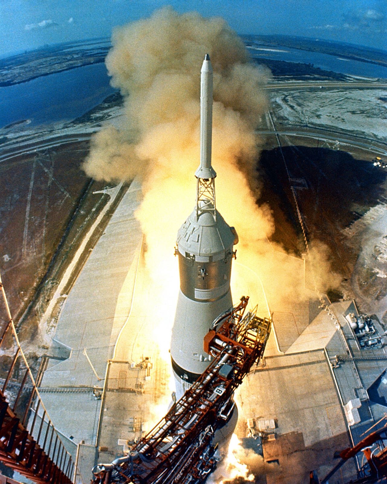
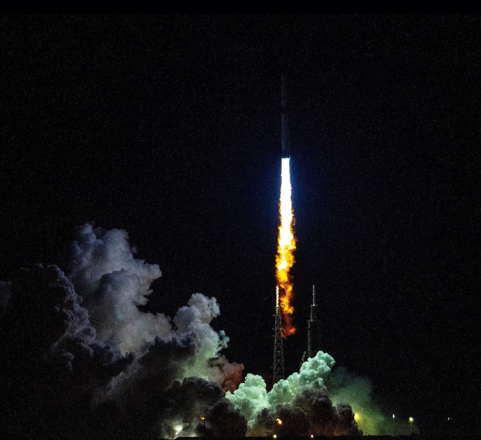
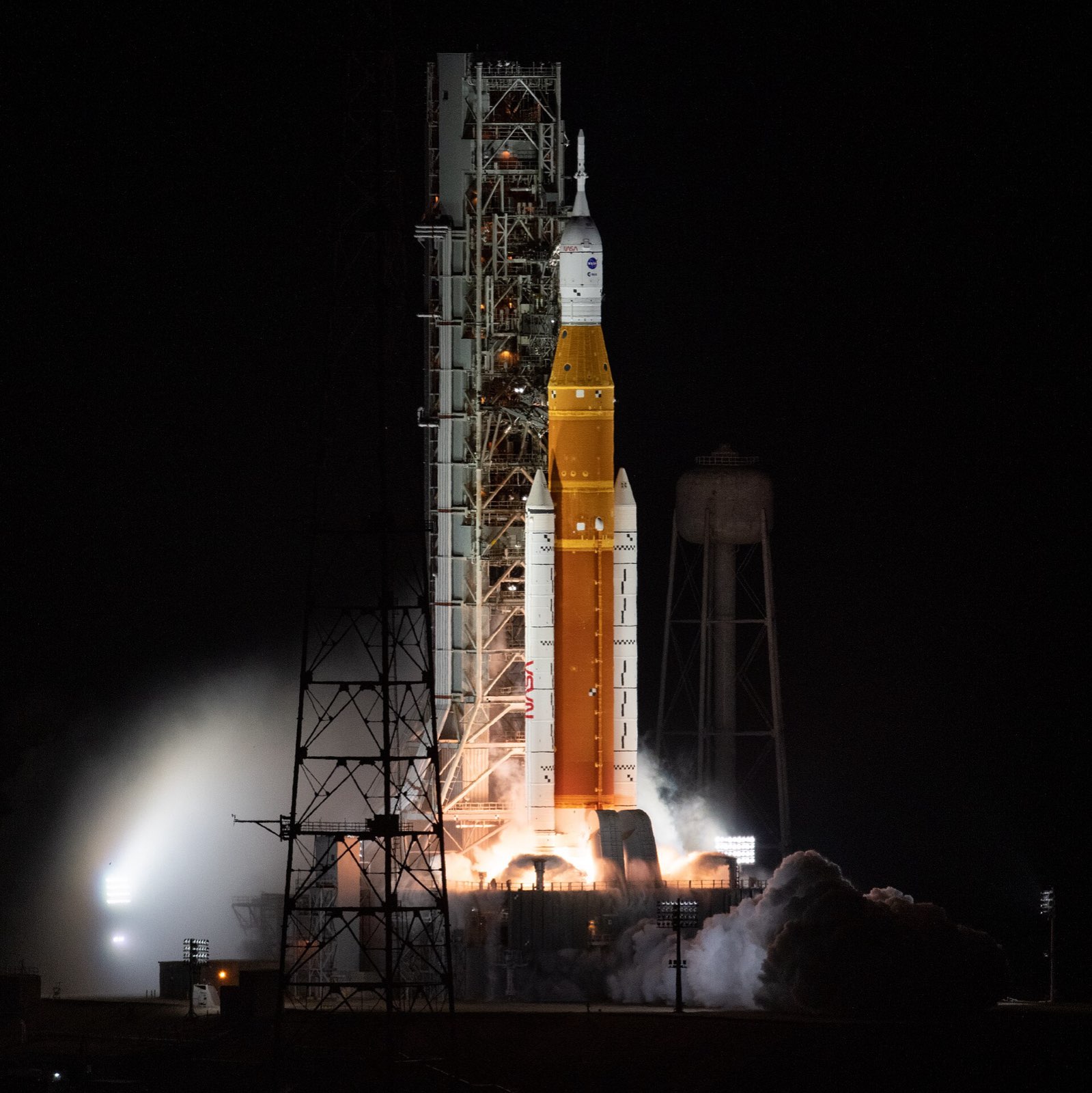
SLS Block 1 with Orion lifting off from Launch Complex 39B at night on Artemis I
NASA

Space Launch System (Block 1)

The Space Launch System is NASA's super heavy-lift rocket for sending Orion and cargo to the Moon.

Launch vehicles
Product IDnasa-sls
Height
322.4 ft (98.3 m)
Fuelled mass
5.74 million lb (2,603 t)
Maximum thrust
8.8 million lb (39,144 kN)
Core stage size
about 212 ft (64.6 m) tall, 27.6 ft (8.4 m) in diameter
Booster burn time
about 2 min 12 s
First launch
16 November 2022 (Artemis I), Launch Complex 39B

In short

The Space Launch System is NASA's heavy-lift rocket for the Artemis missions. NASA calls it the only rocket that can send the Orion spacecraft and its four astronauts, along with large cargo, directly to the Moon. The Block 1 version stands 322.4 feet tall and weighs 5.74 million pounds when fuelled. It first flew on 16 November 2022.

The core stage is welded aluminium, covered in sprayed foam. The two solid boosters use steel cases that flew before, on space shuttle missions. Reusing shuttle hardware was a goal of the design: the boosters add a fifth segment to the shuttle's four, and the four main engines are RS-25s.

Application

NASA's heavy-lift rocket for sending Orion and cargo to the Moon. It stacks a large welded aluminium core stage, two reused-case steel solid boosters and a small upper stage.

How it is built

Core stage

The core stage is made of 10 barrel sections, four domes and seven rings. Each barrel has eight aluminium panels, joined by bolts or by friction stir welding, in which a spinning tool stirs the metal together. The intertank, which joins the two propellant tanks, is the only bolted section.

  • Core stage barrel sections
  • Tank domes (gore panels)
  • Intertank

Tanks and engine section

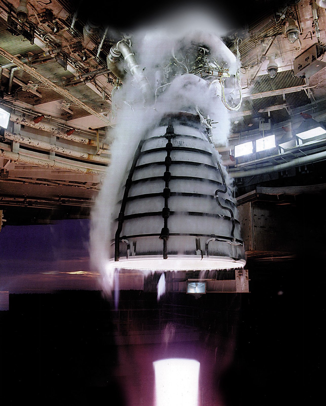
The hydrogen tank is 27.6 feet across and 130 feet tall, and it holds 537,000 gallons. The oxygen tank holds 196,000 gallons. Four RS-25 engines sit in the engine section, where a thrust structure carries their push into the stage and a boat tail fairing shields them from launch heat.

  • Liquid hydrogen tank
  • Liquid oxygen tank
  • RS-25 engines (x4)
  • Engine thrust structure
  • Aerodynamic boat tail fairing

Insulation

A robot sprays flexible polyurethane foam over the outside of the core stage tanks. Cork is used alongside the foam for thermal protection. On the launch vehicle stage adapter, technicians spray the insulation by hand, and it turns orange in sunlight.

  • Core stage tank exterior insulation
  • Core stage thermal protection (additional)
  • Spray-on insulation

Solid boosters

Each booster is 177 feet tall and 12 feet across, with five propellant segments in steel cases that flew on space shuttle missions. Together they give 7.2 million pounds of thrust for about 2 minutes 12 seconds, then fall into the Atlantic Ocean. Each nozzle swivels to steer.

  • Booster cases
  • Booster propellant
  • Five-segment solid rocket motors (x2)
  • Gimballing ablative nozzle (x2)
  • Case insulation and liner (asbestos-free)

Upper elements

The interim upper stage is a modified Delta IV stage with one RL10B-2 engine. The launch vehicle stage adapter is a friction-stir welded shell of two cones and two rings, 27.5 feet tall. The Orion stage adapter is lightweight aluminium, 18 feet across, and holds a diaphragm that keeps hydrogen out of Orion.

  • ICPS stage structure (modified Delta Cryogenic Second Stage)
  • RL10B-2 engine (x1)
  • Cone and ring sections (two cones, two rings)
  • Orion stage adapter
  • Hydrogen barrier diaphragm
Where the parts areNumber of parts we have listed in each group
  • Solid rocket boosters (Northrop Grumman)11
  • Core stage (Boeing)10
  • Interim Cryogenic Propulsion Stage (United Launch Alliance)7
  • Core stage structure6
  • RS-25 engine installation5
  • Launch vehicle stage adapter (Teledyne Brown Engineering)4
  • Thermal protection2
  • Solid rocket boosters2
  • Upper elements2
  • Orion stage adapter (NASA Marshall)2

What it is made of

  • Aluminium alloy 2219

    A test barrel segment of the liquid hydrogen tank. NASA does not name the alloy of the flight panels.

  • Aluminium

    Panels and domes of the core stage, and the lightweight Orion stage adapter. NASA names no alloy for these.

  • Polyurethane foam

    Flexible foam sprayed by robot onto the outside of the core stage tanks.

  • Cork

    Extra thermal protection on parts of the vehicle, alongside the foam.

  • Steel

    The booster cases, reused from space shuttle flights. NASA does not give the grade.

The materials by familyHow many of the parts that name a material use each one
  • Aluminium8
  • Polymers and foams2
  • Stainless steel1

How it connects to other things

Four RS-25 engines, made by Aerojet Rocketdyne, power the core stage, and one RL10B-2 powers the upper stage. For the first four missions, 14 of the RS-25s are shuttle engines that have already flown. Boeing is prime contractor for the core stage and Northrop Grumman leads the boosters. United Launch Alliance makes the upper stage, a modified Delta IV stage.

Engines

  • RS-25 engine

    Aerojet Rocketdyne

    Core stage: four engines, in every SLS configuration

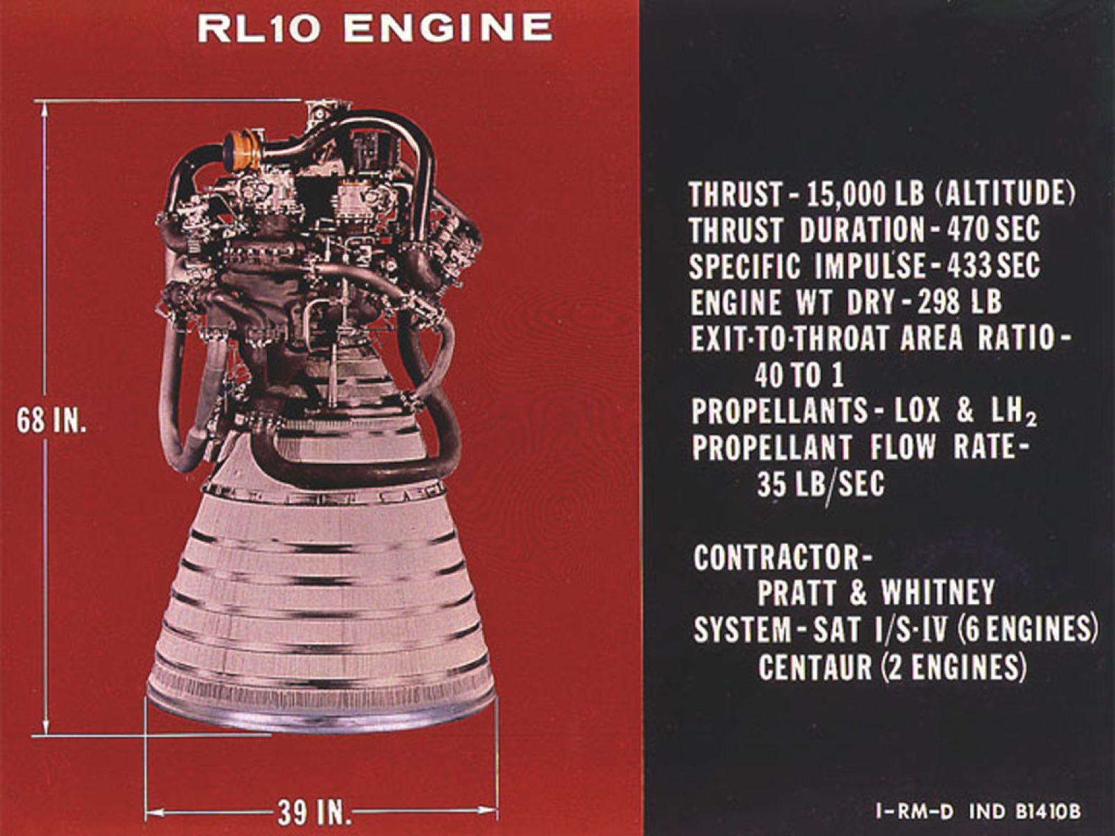
  • RL10 engine

    Aerojet Rocketdyne

    ICPS: one RL10B-2 engine (24,750 lbf)

    1 more detail

    Planned Exploration Upper Stage (Block 1B): four RL10C-3 engines

Carries

Launches

  • Orion spacecraft

    NASA

    Orion sits on top of SLS (on the Orion stage adapter) for Artemis I and II

Builds on

  • Space Shuttle

    Reuses shuttle components and design heritage

Built on

  • Space Shuttle solid rocket booster

    Booster adds a fifth segment to the four-segment shuttle design

  • Delta Cryogenic Second Stage (Delta IV)

    ICPS is a modified Delta IV upper stage

Made or supplied by

  • Boeing

    Prime contractor for the core stage (and the Exploration Upper Stage)

  • Northrop Grumman

    Lead contractor for the solid rocket boosters and separation motors

  • Aerojet Rocketdyne

    Maker of the RS-25

    1 more detail

    Makes the ICPS RL10 engine in West Palm Beach, Florida

  • L3Harris Technologies

    Upgrading an inventory of 16 RS-25 engines to SLS requirements

    1 more detail

    Named as maker of the ICPS RL10 engine

  • United Launch Alliance

    Builds the ICPS

  • Teledyne Brown Engineering

    Builds the launch vehicle stage adapter

  • NASA Marshall Space Flight Center

    Builds the Orion stage adapter in house

Products that share an engine or part with this one

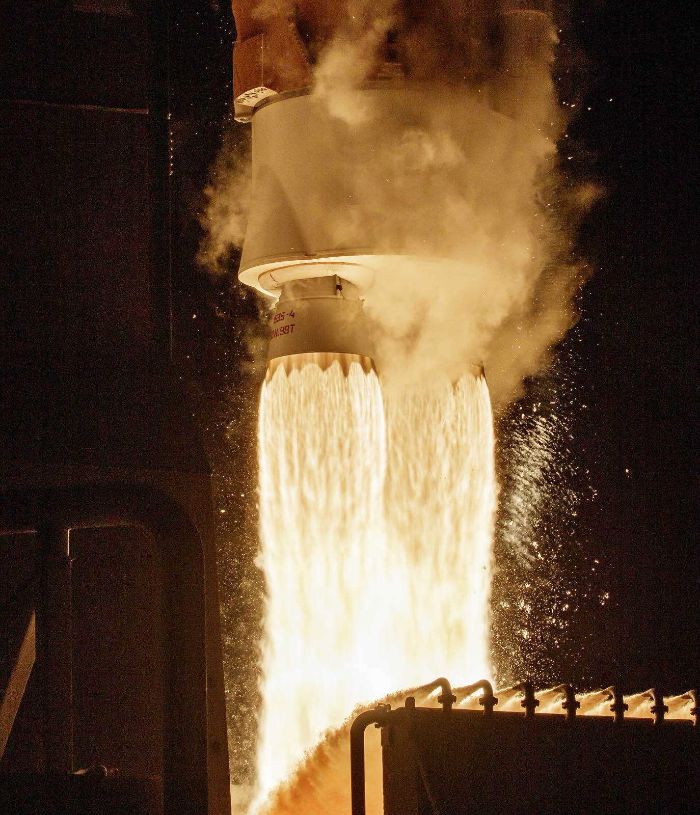
  • Atlas V

    United Launch Alliance

    How it is used

    RL10 engine. Here: ICPS: one RL10B-2 engine (24,750 lbf). There: Common Centaur: one engine (SEC) or two (DEC); RL10A-4-2 in the 2010 guide, RL10C-1 now.

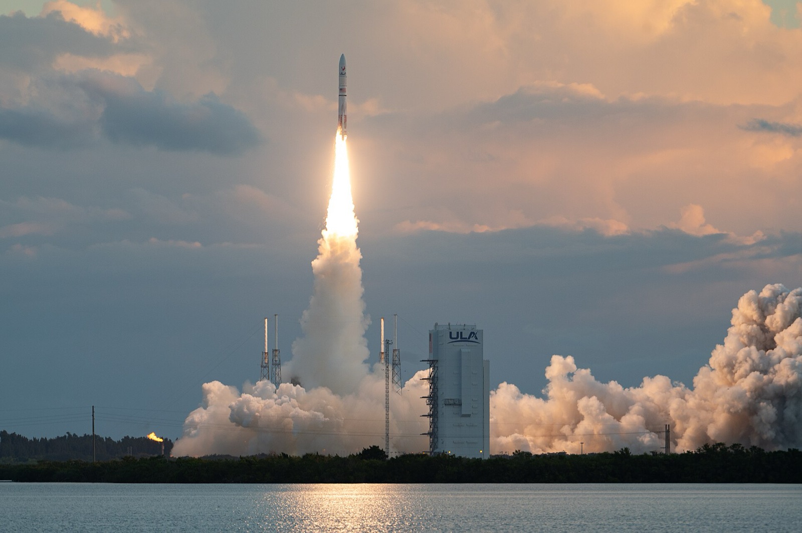
  • Vulcan Centaur

    United Launch Alliance

    How it is used

    RL10 engine. Here: ICPS: one RL10B-2 engine (24,750 lbf). There: Centaur V: two RL10C-1-1A engines, 23,825 lbf each.

Products that use the same materials

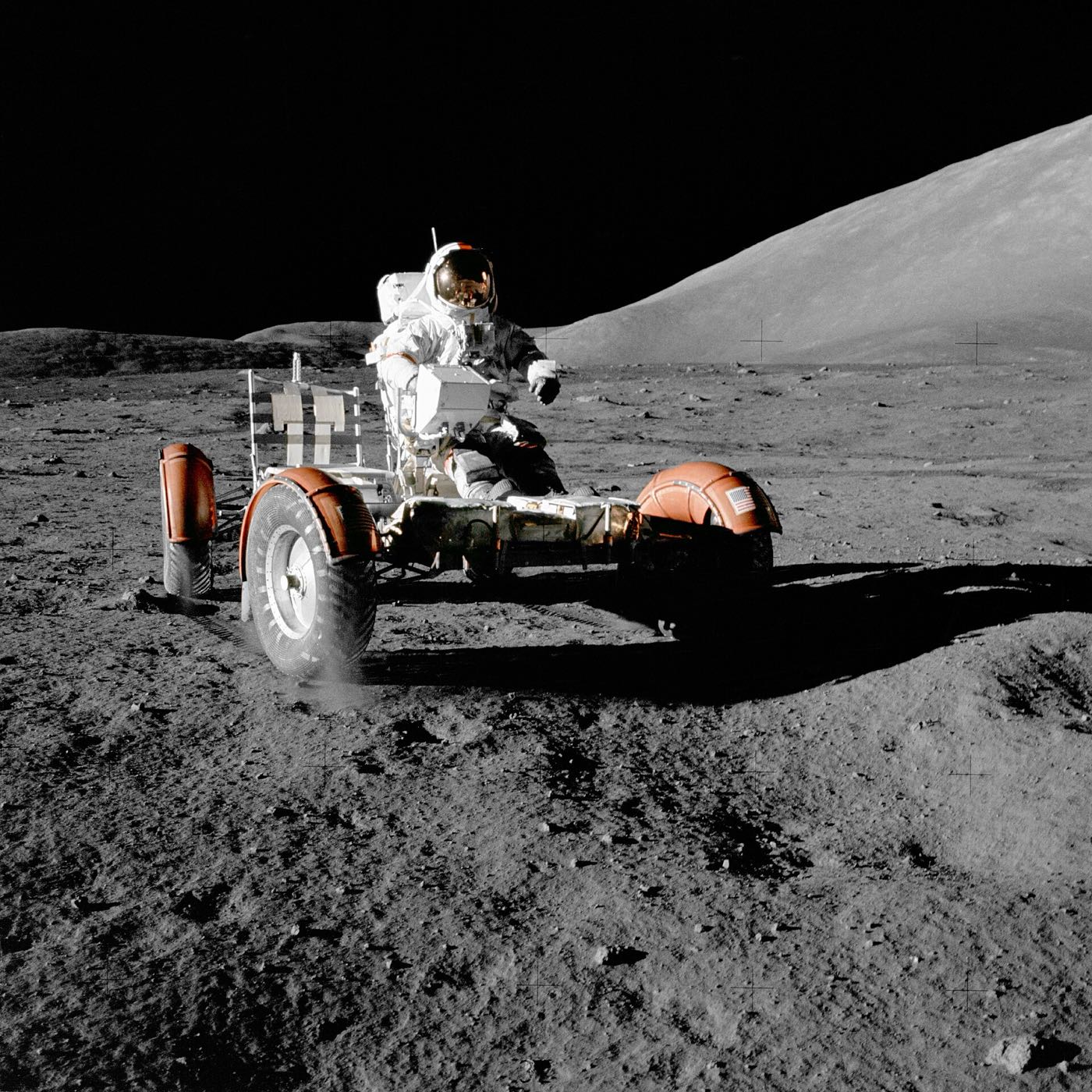
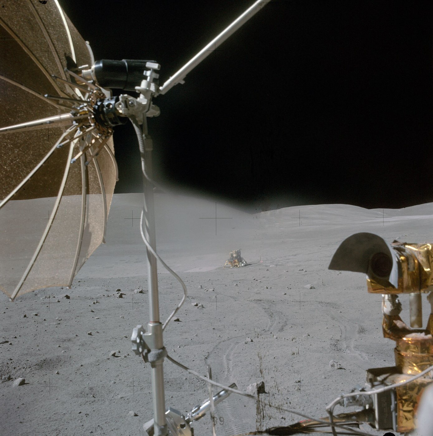
  • Apollo Lunar Roving Vehicle

    Boeing

    AluminiumAl 2219 aluminium alloy
    Where each one is used

    Aluminium. Here: Core stage barrel sections; Engine section and more. There: Hub and wheel disc (MESH-1 prototype wheel).

    Al 2219 aluminium alloy. Here: Liquid hydrogen tank barrel segment (test article). There: Frame.

  • Apollo Lunar Module (LM)

    Grumman / NASA

    AluminiumAl 2219 aluminium alloy
    Where each one is used

    Aluminium. Here: Core stage barrel sections; Engine section and more. There: Cabin front-face, RCS cluster trusses, decks and bulkheads; Micrometeoroid shield and more.

    Al 2219 aluminium alloy. Here: Liquid hydrogen tank barrel segment (test article). There: Ascent-stage cabin, midsection and aft equipment bay shell.

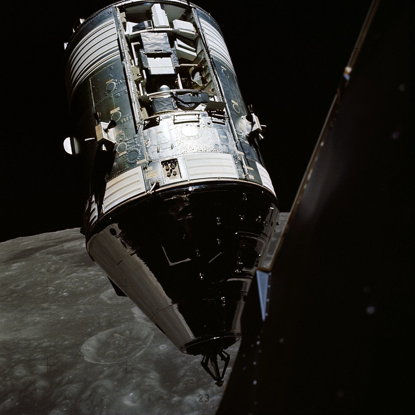
  • Apollo Command and Service Module

    North American Aviation

    Aluminiumsteel
    Where each one is used

    Aluminium. Here: Core stage barrel sections; Engine section and more. There: Radial beams; Crushable ribs (x4) and more.

    steel. Here: Booster cases. There: Crew couch frames (x3); Couch shock-attenuating struts (x8).

  • Lunar Reconnaissance Orbiter (LRO)

    NASA Goddard Space Flight Center

    Aluminiumsteel
    Where each one is used

    Aluminium. Here: Core stage barrel sections; Engine section and more. There: Primary structure (heating/cooling panel, edge members, fittings, brackets); Optical-bench heater aluminum tape and more.

    steel. Here: Booster cases. There: Battery cell can.

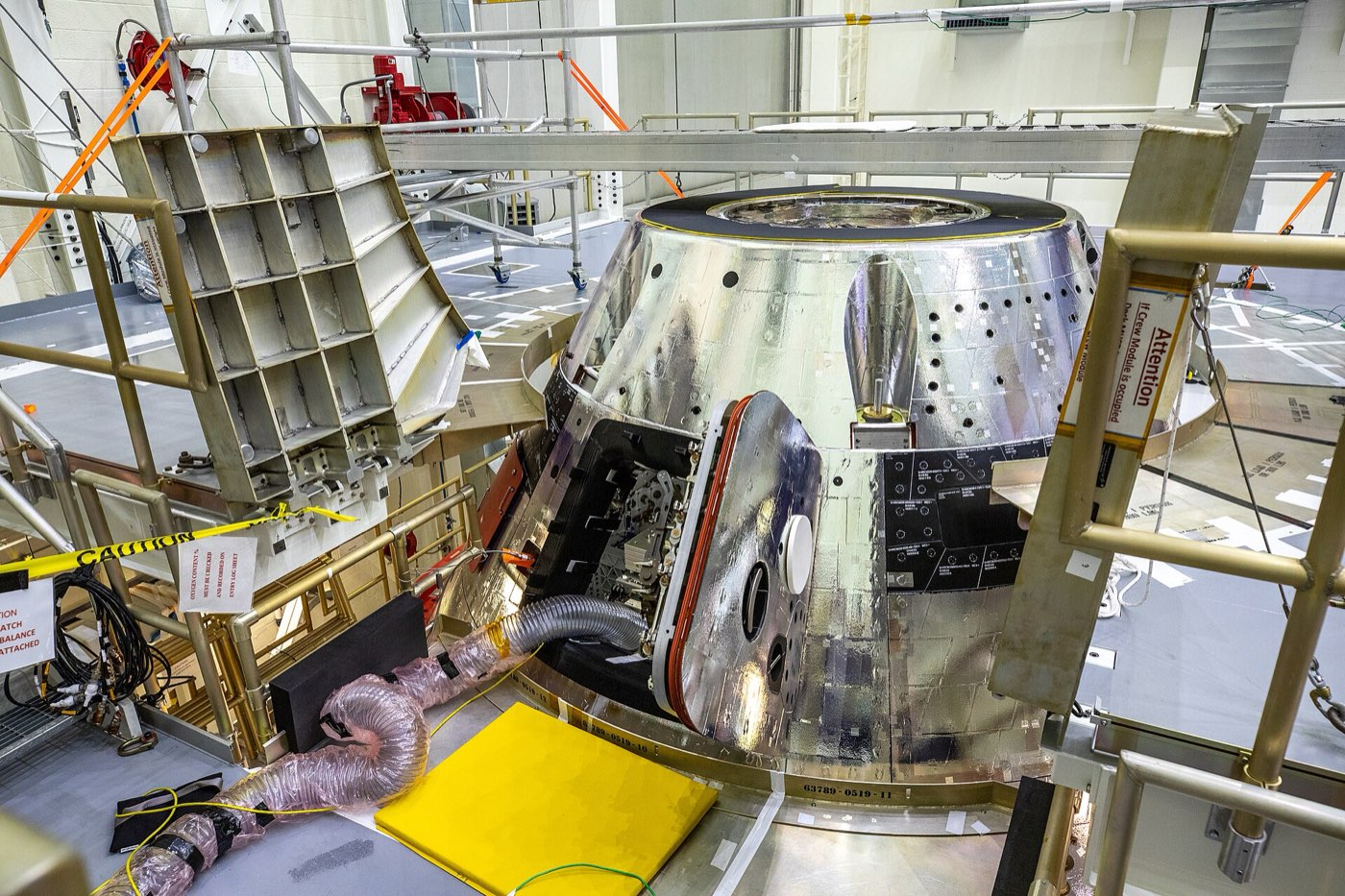
  • Orion spacecraft

    NASA

    AluminiumAl 2219 aluminium alloy
    Where each one is used

    Aluminium. Here: Core stage barrel sections; Engine section and more. There: Pressure vessel (seven large pieces, friction-stir welded); Backbone assembly (floor structure) and more.

    Al 2219 aluminium alloy. Here: Liquid hydrogen tank barrel segment (test article). There: Longeron (Orion ground test article).

  • Saturn V

    NASA

    AluminiumAl 2219 aluminium alloy
    Where each one is used

    Aluminium. Here: Core stage barrel sections; Engine section and more. There: S-IVB forward skirt, aft skirt, thrust structure and aft interstage.

    Al 2219 aluminium alloy. Here: Liquid hydrogen tank barrel segment (test article). There: LOX tank skin.

What we do not know

NASA names the main metals but publishes no part-by-part list. It does not give the alloy of the flight tank panels or the grade of the booster steel. The booster insulation and nozzle materials, the metals inside the RS-25 and RL10 engines, and the material of the launch vehicle stage adapter are not given either.

The detailed data

What is written above is built from these numbers and quotes. Each row links to the page it was taken from. Get all of it as JSON, or ask our MCP server.

Features

  • Core stage tanks are built from friction-stir welded aluminium
  • Two five-segment solid boosters repurpose shuttle steel cases

Specifications

WhatValue
Height322.4 ft (98.3 m)
Mass fueled5.74 million lb (2,603 t)
Maximum thrust8.8 million lb (39,144 kN)
Core stage diameter27.6 ft (8.4 m)
Booster length177 ft
Booster thrust3.6 million lb each (maximum)
First launch16 November 2022 (Artemis I), Launch Complex 39B
Core stage sizeabout 212 ft (64.6 m) tall, 27.6 ft (8.4 m) in diameter
Core stage fuelled mass, excluding engines2.4 million lb (1,088 t)
Core stage construction10 barrel sections, 4 dome sections, 7 rings
Liquid oxygen tank capacity196,000 gal (741,941 L)
Core stage burn timeroughly 480 s
RS-25 sizeabout 14 ft (4.3 m) tall, 8 ft (2.4 m) diameter
RS-25 thrust, four enginesabout 2 million lbf for the eight-minute climb
Booster size and mass177 ft tall, 12 ft diameter, 1.6 million lb loaded
Booster thrust, pair7.2 million lbf (32,027 kN)
Booster burn timeabout 2 min 12 s
Launch vehicle stage adapter height27.5 ft (8.4 m)
Orion stage adapter size18 ft (5.5 m) diameter, 5 ft (1.5 m) tall
Exploration Upper Stage thrustabout 97,000 lbf from four RL10C-3 engines
Block 2 liftoff thrust9.4 million lb (Block 1: 8.8 million lb)

Materials in detail

Each material named in the sources: where it is used here, which other products use it, and its key numbers when its material page exists.

  • Aluminium

    Used in 6 partsCore stage barrel sections · Engine section · Liquid oxygen tank · +3 more

    Weight
    2.7 g/cm3
    Electrical conduction
    2.6458 µΩ·cm
    Heat conduction
    220 W/(m·K)
    Also in 33 other products
  • Al 2219 aluminium alloy

    aluminium-2219

    Used in 1 partLiquid hydrogen tank barrel segment (test article)

    Material page coming soon
  • cork (alongside spray-on foam)

    cork

    Used in 1 partCore stage thermal protection (additional)

    Material page coming soon
  • flexible polyurethane foam

    polyurethane-foam-spray-on

    Used in 1 partCore stage tank exterior insulation

    Material page coming soon
  • PBAN, ammonium perchlorate and aluminium powder

    pban-ap-aluminium-propellant

    Used in 1 partBooster propellant

    Material page coming soon
  • steel (grade not stated)

    steel-grade-unstated

    Used in 1 partBooster cases

    Material page coming soon

Every part we have

NASA names the main metals and insulation but gives no per-part alloy list for the flight hardware. Components, suppliers and links were added from public sources. A material is left blank where no source states it.

Material IDs

aluminium-2219aluminiumpolyurethane-foam-spray-oncorksteel-grade-unstatedpban-ap-aluminium-propellantaluminium-unstated
Core stage structure6
PartMaterialFinish and standardMade by
Liquid hydrogen tank barrel segment (test article)“made of Al 2219, an aerospace aluminum alloy” Al 2219 aluminium alloyaluminium-2219 — Core stage
Core stage barrel sections“Each cylindrical barrel section consists of eight aluminum panels” aluminium (alloy not stated in this source)aluminium — —
Engine section“welded aluminum isogrid panels” aluminium (alloy not stated)aluminium — —
Liquid oxygen tank“sections of isogrid aluminum panels and two domes” aluminium (alloy not stated)aluminium — —
Forward skirt“The aluminum isogrid structure” aluminium (alloy not stated)aluminium — —
Tank domes (gore panels)“Gores are preformed aluminum alloy dome segments” aluminium alloy (not named)aluminium — —
Thermal protection2
PartMaterialFinish and standardMade by
Core stage tank exterior insulation“flexible polyurethane foam” flexible polyurethane foampolyurethane-foam-spray-on — —
Core stage thermal protection (additional)“materials such as cork, provides thermal protection for every” cork (alongside spray-on foam)cork — —
Solid rocket boosters2
PartMaterialFinish and standardMade by
Booster cases“All booster components use steel cases repurposed from cases used on prior space shuttle flights” steel (grade not stated)steel-grade-unstated — —
Booster propellant“perchlorate, and aluminum powder” PBAN, ammonium perchlorate and aluminium powderpban-ap-aluminium-propellant — —
Upper elements2
PartMaterialFinish and standardMade by
Orion stage adapter“made of lightweight aluminum” lightweight aluminiumaluminium — —
Launch vehicle stage adapter“Teledyne Brown Engineering manufactures the launch” Not said — —
Core stage (Boeing)10
PartMaterialFinish and standardMade by
Liquid hydrogen tankHolds the RS-25 fuel; five barrel sections and two domes“The liquid hydrogen fuel tank is 27.6 ft. (8.4 m) in diameter and 130 ft. (39.7 m) tall.” Not said — —
IntertankJoins the two propellant tanks and is the forward attach point for the boosters; the only bolted section“The intertank measures 27.6 ft. (8.4 m) in diameter and 21.8 ft. (6.7 m) tall.” Not said — —
Engine thrust structureCarries the RS-25 thrust into the stage; houses the engine ducts and thrust vector control“the engine section houses four RS-25 main engines, the engine thrust structure, propellant ducts, various avionics systems” Not said — —
Aerodynamic boat tail fairingChannels airflow and shields the engines from extreme launch temperatures“An aerodynamic boat tail fairing at the bottom channels airflow and protects the engines from extreme temperatures during launch.” Not said — —
Liquid hydrogen feedlines (x4)Carry LH2 from the tank aft end to the RS-25 engines“The aft end of the liquid hydrogen tank includes four liquid hydrogen feedlines to the RS-25 engines.” Not said — —
Liquid oxygen downcomer ducts (x2)Carry LOX from the intertank down to the engine section“through a pair of “downcomer” ducts that exit the intertank on opposite sides” Not said — —
Main propulsion system (ducts, valves, pressurization)Supplies and controls propellant, helium and nitrogen flow“consists of the ducts, valves, and other equipment that supply and control the flow of liquid hydrogen and liquid oxygen propellants” Not said — —
Core stage flight computers (forward skirt)Run the Block 1 vehicle in flight; software written at NASA Marshall“The core stage forward skirt contains the flight computers for the Block 1 SLS rocket.” Not said — Supplier: Boeing (core stage lead contractor)
Cabling (562 cables) and sensors (775)Wiring and instrumentation, 231 cables in the engine section alone“There are 562 cables in the core stage.” Not said — —
Rear-facing cameras in the intertank (x2)Watch the vehicle from the intertank, with the tank interfaces“including two rear-facing cameras and interfaces to the liquid hydrogen and liquid oxygen tanks” Not said — —
RS-25 engine installation5
PartMaterialFinish and standardMade by
RS-25 engines (x4)Main engines of the core stage, liquid hydrogen and liquid oxygen“The SLS core stage contains four RS-25 engines, their liquid hydrogen and liquid oxygen propellant supply” Not said — Supplier: Aerojet Rocketdyne (now L3Harris)
RS-25 engine controllers (x4, new for SLS)Onboard computer that runs start, shutdown, throttle, mixture ratio and engine health“Each engine has an onboard computer that automatically controls start and shutdown” Not said — —
RS-25 nozzle insulation (new for SLS)Protects the nozzles from booster exhaust“the addition of nozzle insulation to protect them from booster exhaust” Not said — —
Engine gimbal hydraulic actuatorsSteer each engine through two planes for pitch, yaw and roll“During ascent, the engines are gimballed through two planes by hydraulic actuators to produce vehicle pitch, yaw, and roll.” Not said — —
Pogo accumulator assembly (3D printed, new-production engines)Shock absorber that regulates LOX movement to stop pogo vibration“The 3-D printed part tested, called the pogo accumulator, is a beachball-sized piece of hardware” Not said — —
Solid rocket boosters (Northrop Grumman)11
PartMaterialFinish and standardMade by
Five-segment solid rocket motors (x2)Burn about two minutes and give more than 75 percent of liftoff thrust“The motor assembly has five segments, each with two case segments filled with rubbery propellant.” Not said — Supplier: Northrop Grumman
Motor igniter (forward segment)Lights the length of the hollow motor so all segments ignite together“The forward segment contains the igniter that fires the length of the hollow motor segments” Not said — —
Gimballing ablative nozzle (x2)Steers the vehicle; wider than the shuttle nozzle“The aft motor segment is attached to an ablative exhaust nozzle that can be gimballed to steer the rocket.” Not said — —
Booster thrust vector control systems (x2)Gimbal the nozzle; boosters give 90 percent of steering in the first two minutes“The thrust vector control system gimbals the exhaust nozzle and steers the vehicle.” Not said — —
Booster separation motors (x16: 4 nose and 4 aft per booster)Push the spent boosters away at motor burnout“Northrop Grumman, lead booster contractor, also produces the booster separation motors” Not said — Supplier: Northrop Grumman
Booster forward assembly (nose cap, frustum, booster forward skirt)Top of the booster; frustum carries four separation motors“The forward skirt assembly includes the nose cap, frustum with four solid fuel booster separation motors, and forward skirt.” Not said — —
Aft skirt assemblyCarries the whole stack weight on the mobile launcher; holds the TVC system“The aft skirt assembly on each booster consists of the aft skirt, the thrust vector control system” Not said — —
Booster avionics and flight termination systemBooster control and safety, housed in the forward skirt“The forward skirt houses booster avionics, the flight termination system, and the core stage attach support posts” Not said — —
Core-stage attach struts (forward and aft)Tie each booster to the core stage“The forward attach struts are also located on the forward segment.” Not said — —
Pyrotechnic separation boltsFire on the attach struts at booster separation“pyrotechnically activated separation bolts on the booster attach struts fire” Not said — —
Case insulation and liner (asbestos-free)Thermal protection of the motor case“New asbestos-free insulation and liner configuration.” Not said — —
Interim Cryogenic Propulsion Stage (United Launch Alliance)7
PartMaterialFinish and standardMade by
ICPS stage structure (modified Delta Cryogenic Second Stage)Interim upper stage that sends Orion to the Moon“ICPS is a modified Delta Cryogenic Second Stage, a proven upper stage used on ULA’s Delta IV family of launch vehicles” Not said — Supplier: United Launch Alliance
RL10B-2 engine (x1)Single liquid hydrogen/liquid oxygen engine of the ICPS“feeding a single Aerojet Rocketdyne RL10B-2 engine producing 24,750 lbs. (110 kN) of thrust” Not said — Supplier: Aerojet Rocketdyne (now L3Harris)
Hydrazine bottles for attitude control (x2)Reaction control; a second bottle was added for SLS“adding a second hydrazine bottle for attitude control” Not said — —
Liquid hydrogen tank (lengthened 18.4 in)Stretched compared with the Delta IV stage“lengthening the liquid hydrogen tank by 18.4 in. (46.7 cm)” Not said — —
Navigation system (new)Replaces the Delta stage navigation hardware“a new navigation system, Orion and launch vehicle stage adapter electrical and mechanical interfaces” Not said — —
RL10 in-flight helium injector purgeSupports engine restart“an RL10 in-flight helium injector purge to support engine restart” Not said — —
Liquid hydrogen vent and relief valve (modified)Tank venting and over-pressure relief“a modified liquid hydrogen vent and relief valve” Not said — —
Launch vehicle stage adapter (Teledyne Brown Engineering)4
PartMaterialFinish and standardMade by
Frangible joint assemblyPneumatically actuated joint that releases the ICPS, adapter and Orion from the core stage“A pneumatically actuated frangible joint assembly at the top of the launch vehicle stage adapter separates the ICPS” Not said — —
Cone and ring sections (two cones, two rings)Friction-stir welded shell“The adapter consists of two cones and two ring sections.” Not said — Supplier: Teledyne Brown Engineering
Spray-on insulationThermal protection applied by hand; turns orange in sunlight“technicians manually apply spray-on insulation, which turns orange in sunlight” Not said — —
Cameras inside the adapterRecord adapter performance and its location after separation“Cameras inside the adapter provide engineers with data on its performance and location in space” Not said — —
Orion stage adapter (NASA Marshall)2
PartMaterialFinish and standardMade by
Secondary payload deployment systemBrackets, harnesses, vibration isolation and an avionics unit that release CubeSats“SLS provided a comprehensive secondary payload deployment system for the CubeSats” Not said — —
Hydrogen barrier diaphragmKeeps gases generated during launch out of Orion“The adapter contains a diaphragm that provides a barrier to prevent gases, such as hydrogen, generated during launch from entering Orion.” Not said — —
Block 1B upper stage (planned)2
PartMaterialFinish and standardMade by
Exploration Upper Stage with four RL10C-3 enginesPlanned replacement for the ICPS from Artemis IV“It is powered by four RL10C-3 engines that produce almost four times more thrust than the one RL10B-2 engine that powers the ICPS.” Not said — Supplier: Boeing (stage); L3Harris (engines)
Universal stage adapter (10,000 cubic ft)Cargo compartment for Block 1B“a new 10,000-cubic-foot universal stage adapter” Not said — —
Avionics1
PartMaterialFinish and standardMade by
Distributed avionics (engines, boosters, ICPS tied to core stage)Core stage computers use data from every element to fly the rocket“The avionics in the engines, boosters, and ICPS are connected to the flight avionics in the core stage.” Not said — —

Standards named

  • Al 2219 (alloy designation) · Core stage test barrel segment

What the sources leave out

Materials not stated in the sources read: alloy of the barrel, isogrid and skirt panels (only the test barrel segment is named Al 2219), booster steel grade, case insulation and nozzle materials, RS-25 and RL10 engine alloys, ICPS tank alloy, launch vehicle stage adapter material. Block 1B composite booster case is mentioned by NASA but is not flown yet. More detail: Alloys of the tank panels, intertank, engine section, LVSA and OSA beyond those in the current entry are not stated. Case steel grade, insulation and nozzle materials of the boosters, the RS-25 and RL10 internals, ICPS tank alloy, and flight computer, avionics and TVC hardware makers are not named in the NASA pages read. RS-25 and RL10 are cross-linked in the engine entries. The NASA SLS page (updated 24 Mar 2026) still describes the Exploration Upper Stage and Block 1B from Artemis IV; one search result (Wikipedia) reported a Feb 2026 cancellation of the EUS and Block 1B that was not confirmed on a NASA page, so re-check the Block 1B rows before publishing them as current. More detail: Alloys of the tank panels, intertank, engine section, LVSA and OSA beyond those in the current entry are not stated. Case steel grade, insulation and nozzle materials of the boosters, the RS-25 and RL10 internals, ICPS tank alloy, and flight computer, avionics and TVC hardware makers are not named in the NASA pages read. RS-25 and RL10 are cross-linked in the engine entries. The NASA SLS page (updated 24 Mar 2026) still describes the Exploration Upper Stage and Block 1B from Artemis IV; one search result (Wikipedia) reported a Feb 2026 cancellation of the EUS and Block 1B that was not confirmed on a NASA page, so re-check the Block 1B rows before publishing them as current.
Where this comes from

6 pages from 1 website

More space products

Collected from public pages and documents, checked 4 Nov 2026.

Published · Updated