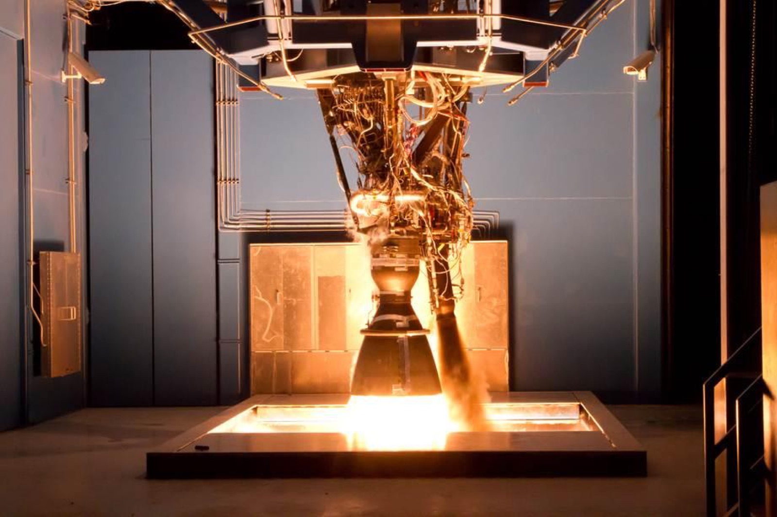
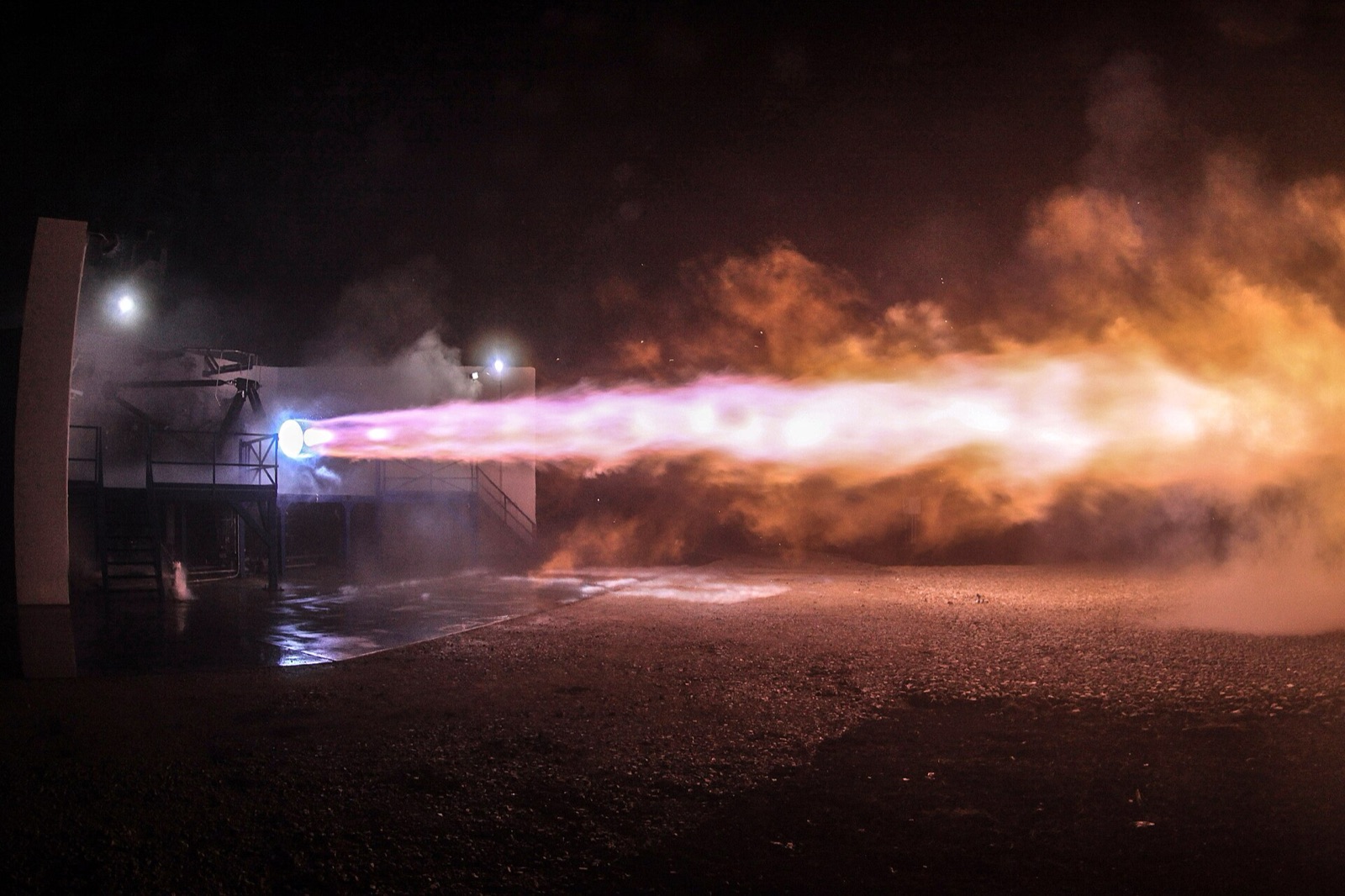
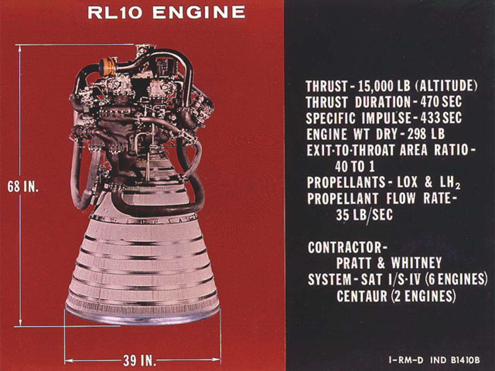
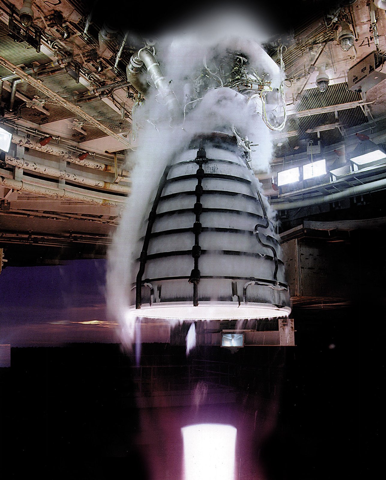
RS-25 engine firing on a Stennis test stand, large nozzle with frost and white exhaust
Aerojet Rocketdyne

RS-25 engine

The RS-25 is the Space Shuttle Main Engine, now used on the core stage of NASA's Space Launch System.

Engines
Product IDaerojet-rs-25
Propellants
Liquid oxygen and liquid hydrogen
Cycle
Staged combustion
Sea-level thrust, shuttle era
About 380,000 lb
Mass
About 7,775 lb
Size
About 14 ft long, 7.5 ft diameter at nozzle exit
Shuttle missions flown
135 space shuttle missions

In short

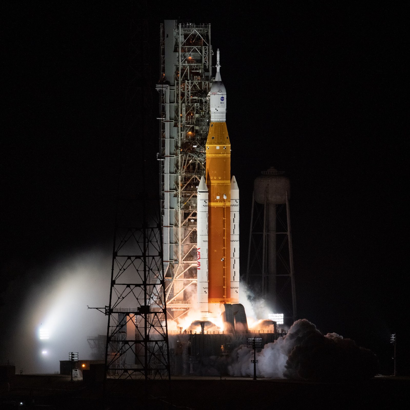
The RS-25 burns liquid hydrogen with liquid oxygen. It began as the Space Shuttle Main Engine, three to an orbiter, and flew on 135 shuttle missions from 12 April 1981. Four now power the core stage of NASA's Space Launch System, which first flew on 16 November 2022.

In its staged-combustion design, two preburners make hot gas that drives the turbopumps, and that exhaust then burns in the main chamber. Hydrogen flowing through channels and tubes cools the chamber and nozzle. Inconel 718, a nickel superalloy, makes up roughly 51 percent of the engine's weight.

Application

NASA’s Space Launch System core stage uses RS-25 engines, the same design that powered the Space Shuttle for 30 years. The engine shows how a copper-alloy liner and a nickel superalloy jacket survive hydrogen-oxygen combustion, so it is a common reference for reusable high-pressure engines.

How it is built

Chamber and liner

The inner wall of the main chamber is NARloy-Z, a copper alloy with silver and zirconium that Rocketdyne developed, cut with 430 coolant channels. An electroformed nickel layer covers the outside, and a jacket of Inconel 718 holds in a pressure of 3,000 psi.

  • Chamber liner (inner wall, 430 coolant channels)
  • Chamber liner exterior
  • Chamber support jacket
  • Main injector (600 coaxial elements)

Nozzle

The nozzle wall is lined with 1,080 stainless steel tubes, each an eighth of an inch across, that carry hydrogen to cool it. Four layers of metallic batting under Nichrome foil insulate the outside. The exhaust leaves the nozzle at 17,000 feet per second.

  • Nozzle coolant tubes (1,080 tubes, brazed to jacket)
  • Nozzle external thermal shield

Preburners and turbopumps

The two preburners have Inconel 718 bodies and burn most of the hydrogen with part of the oxygen to drive the turbopumps. The high-pressure fuel pump, the engine's most complex part, spins at about 36,000 rpm. New oxygen-pump ball bearings are silicon nitride, a ceramic 30 percent harder and 40 percent lighter than steel.

  • Preburner body and inlet manifold
  • High-pressure fuel turbopump (HPFTP)
  • High-pressure oxidizer turbopump bearings (Block I)

Controls and valves

The shuttle-era controller, built by Honeywell with two redundant computers, ran start-up, throttling and shutdown, updating every 20 milliseconds. Five hydraulic valves controlled the propellant flow. Two actuators swivelled each engine, up to 10.5 degrees in pitch and 8.5 in yaw.

  • Main engine controller
  • Five hydraulically actuated propellant valves
  • Thrust vector control actuators (x2: pitch and yaw)

Changes for SLS

SLS engines have new controllers and software, and nozzle insulation to protect them from booster exhaust. A 3D-printed pogo accumulator, a beachball-sized shock absorber that regulates the oxygen flow, removed more than 100 welds. New-production engines, from Artemis V, are rated for 111 percent thrust against the shuttle engines' limit of 109.

  • New engine controller and nozzle insulation (SLS upgrades)
  • Pogo accumulator assembly (3D printed)
Where the parts areNumber of parts we have listed in each group
  • Turbomachinery10
  • Powerhead, injectors and ignition7
  • Valves, controller and actuators7
  • Nozzle structure4
  • Main combustion chamber3
  • Nozzle2
  • New-production hardware2
  • Hot gas manifold1
  • Preburners1
  • Heat exchanger1

What it is made of

  • NARloy-Z

    The inner wall of the main combustion chamber, a copper-silver-zirconium alloy cut with 430 coolant channels.

  • Inconel 718

    The chamber support jacket and preburner bodies. It is in about 1,500 components.

  • Electroformed nickel

    The outer layer of the chamber liner, applied by electroforming.

  • Stainless steel

    The 1,080 nozzle cooling tubes and the oxygen heat exchanger coil. NASA does not name the grades.

  • Silicon nitride

    Ball bearings in the high-pressure oxygen pump of the Block I engine.

  • Nichrome

    Foil and screen over the batting on the outside of the nozzle.

The materials by familyHow many of the parts that name a material use each one
  • Nickel and cobalt alloys5
  • Other2
  • Stainless steel2
  • Copper1
  • Semiconductors1
  • Polymers and foams1

How it connects to other things

Three RS-25s sat at the back of each Space Shuttle orbiter, and four power the SLS core stage. The first four SLS missions use 14 flight-proven shuttle engines and two assembled from shuttle-era parts. Pratt & Whitney Rocketdyne made the nozzle, chamber and powerhead. Honeywell built the controller and HR Textron the valve actuators. L3Harris has restarted production, aiming for a 30 percent lower cost.

Used in

  • Space Shuttle orbiter (three engines)

    Three engines per orbiter: centre, left, right

    2 more details

    Engines are mounted on the aft end of the orbiter

    First flown on STS-1, 12 April 1981

  • Space Launch System (Block 1)

    NASA

    Core stage: four engines, in every SLS configuration

    1 more detail

    Formerly the Space Shuttle Main Engine

Launches

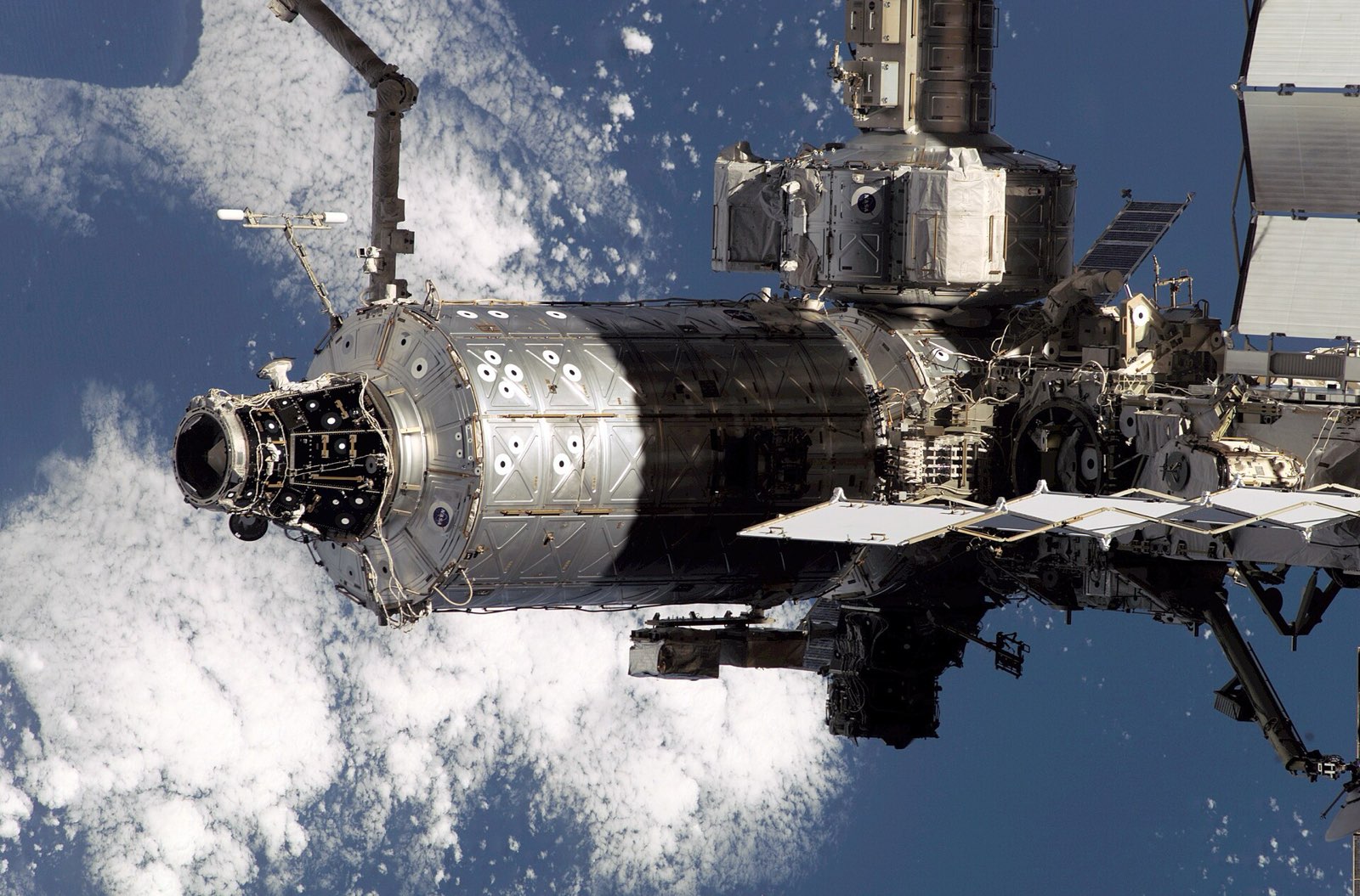
  • Destiny laboratory module (ISS)

    NASA / Boeing

    Main engines of the orbiter that lifted Destiny; launcher engine, not carried by the vehicle

    1 more detail

    Identity link: RS-25 is the former Space Shuttle Main Engine; launcher engine, not carried by the vehicle

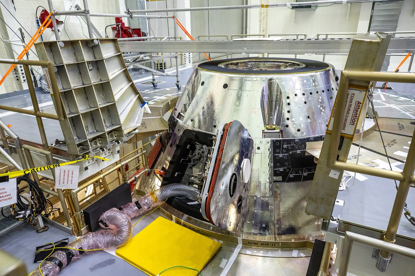
  • Orion spacecraft

    NASA

    Four RS-25 engines on the SLS core stage lift Orion; launcher engine, not carried by the capsule

Builds on

  • Space Shuttle Main Engine (SSME)

    RS-25 is the SSME, reused on SLS: 14 flight-proven engines plus two assembled from shuttle parts for the first four missions

Made or supplied by

  • Pratt & Whitney Rocketdyne (earlier Rocketdyne, now Aerojet Rocketdyne / L3Harris)

    Nozzle, chamber, powerhead, low-pressure pumps, valves and ducts

  • L3Harris Technologies

    Restarted engine production (30 percent cost-reduction goal)

  • Honeywell

    Main engine controller, Clearwater, Florida

  • HR Textron (Hydraulic Research)

    Engine valve actuators, Valencia, California

  • Special Metals Corporation

    Inconel alloy 718 named as a key alloy

  • Martin Metals

    Developed the nickel-based super alloy of the original turbine blades

Products that use the same materials

  • AJ10-190 engine

    Aerojet Rocketdyne

    stainless steelstructural nickel
    Where each one is used

    stainless steel. Here: Nozzle coolant tubes (1,080 tubes, brazed to jacket); Oxidizer heat exchanger coil. There: Chamber liner.

    structural nickel. Here: Chamber liner exterior. There: Chamber outer shell.

What we do not know

NASA's detailed report covers the shuttle-era engine, so the SLS version's changes are described only in outline. The grades of the turbine blade superalloy, nozzle tubes and heat exchanger tube are not named, and neither are the materials of most rotors, injectors, valves and ducts.

The detailed data

What is written above is built from these numbers and quotes. Each row links to the page it was taken from. Get all of it as JSON, or ask our MCP server.

Features

  • Dual preburners drive the high-pressure turbopumps; turbine exhaust burns in the main chamber
  • Chamber and nozzle are cooled by hydrogen flowing through channels and tubes
  • Engine alloys were developed for extreme temperature swings

Specifications

WhatValue
PropellantsLiquid oxygen and liquid hydrogen
CycleStaged combustion
Sea-level thrust (rated power level)About 380,000 lb
Throttle range67 to 109 percent of rated power
MassAbout 7,775 lb
SizeAbout 14 ft long, 7.5 ft diameter at nozzle exit
Chamber pressure3,000 psi (main combustion chamber)
Nozzle area ratio77.5:1
Thrust, sea level, full power levelabout 420,000 lbf at 109 percent
Thrust levels, vacuumabout 470,000 / 490,000 / 512,000 lbf at 100 / 104.5 / 109 percent
First SLS flight with four RS-25 engines16 Nov 2022 (Artemis I) from Launch Complex 39B
First Space Shuttle flight with three RS-25 enginesSTS-1, Columbia, 12 April 1981
SLS operating thrust109 percent, about 512,300 lbf (2,279 kN) in vacuum
Part countabout 50,000 parts, 7,000 tracked for replacement
Flight experience in the shuttle programover 57 hours of flight time and 246.7 hours of ground tests
Design life55 starts and 27,000 s of run time
Shuttle missions flown135 space shuttle missions
Burnabout eight and a half minutes from ignition to main engine cutoff
Propellant burnedover 1.6 million lb (about 528,000 gal) per flight
Nozzle size10.3 in diameter at the throat, 90.7 in at the exit
Nozzle propellant flow1,035 lb/s at 100 percent power
Nozzle exit velocity17,000 ft/s
Fleet leaderEngine 2019 flew nineteen missions
New-production affordabilitydesign changes and advanced manufacturing to eliminate more than 700 welds and 700 parts
New-production enginesArtemis V onward, rated for 111 percent thrust
Engines being built24 engines

Materials in detail

Each material named in the sources: where it is used here, which other products use it, and its key numbers when its material page exists.

  • Inconel alloy 718

    inconel-718

    Used in 3 partsPreburner body and inlet manifold · Chamber support jacket · Inconel 718 across about 1,500 components

    Material page coming soon
  • stainless steel (grade not stated)

    stainless-steel

    Used in 2 partsNozzle coolant tubes (1,080 tubes, brazed to jacket) · Oxidizer heat exchanger coil

    Material page coming soon
  • alloy 903

    alloy-903

    Used in 1 partHot gas manifold outer wall liner

    Material page coming soon
  • Kevlar jacket over foam

    kevlar

    Used in 1 partLow-pressure fuel turbopump housing insulation

    Also in 1 other product
    Material page coming soon
  • NARloy-Z (copper-silver-zirconium)

    narloy-z

    Used in 1 partChamber liner (inner wall, 430 coolant channels)

    Material page coming soon
  • Nichrome foil and screen over metallic batting

    nichrome

    Used in 1 partNozzle external thermal shield

    Material page coming soon
  • nickel-based super alloy (grade not stated)

    nickel-base-superalloy

    Used in 1 partHigh-pressure fuel turbopump turbine blades (original design)

    Material page coming soon
  • silicon nitride

    silicon-nitride

    Used in 1 partHigh-pressure oxidizer turbopump bearings (Block I)

    Material page coming soon
  • structural nickel

    electroformed-nickel

    Used in 1 partChamber liner exterior

    Also in 1 other product
    Material page coming soon

Every part we have

Chamber, preburner, manifold, nozzle and heat-exchanger materials are named in the NASA HAER report for the Shuttle-era Block II engine. Turbopump rotors and injectors are mostly unnamed. Components, suppliers and links were added from public sources. A material is left blank where no source states it.

Material IDs

alloy-903inconel-718narloy-zelectroformed-nickelstainless-steelnichromenickel-base-superalloysilicon-nitridekevlar
Hot gas manifold1
PartMaterialFinish and standardMade by
Hot gas manifold outer wall liner“The structural outer walls consisted of an alloy 903 sheet metal liner” alloy 903alloy-903 — Two halves joined by electron-beam welding
Preburners1
PartMaterialFinish and standardMade by
Preburner body and inlet manifold“The structural body and inlet manifold of each preburner were machined from Inconel alloy 718” Inconel alloy 718inconel-718 — —
Main combustion chamber3
PartMaterialFinish and standardMade by
Chamber liner (inner wall, 430 coolant channels)“Rocketdyne developed NARloy-Z, a high conductivity copper-based alloy that contained silver and zirconium.” NARloy-Z (copper-silver-zirconium)narloy-z — —
Chamber liner exterior“The exterior of the liner was made from structural nickel which was applied by an electroforming process.” structural nickelelectroformed-nickel — —
Chamber support jacket“The support jacket of the main combustion chamber was made from Inconel alloy 718.” Inconel alloy 718inconel-718 — —
Nozzle2
PartMaterialFinish and standardMade by
Nozzle coolant tubes (1,080 tubes, brazed to jacket)“The inside wall of the nozzle was lined with 1,080, 1/8” stainless steel cooling tubes that carried hydrogen.” stainless steel (grade not stated)stainless-steel — —
Nozzle external thermal shield“four layers of metallic batting covered with a metallic foil (Nichrome)” Nichrome foil and screen over metallic battingnichrome — —
Heat exchanger1
PartMaterialFinish and standardMade by
Oxidizer heat exchanger coil“continuous piece of coiled stainless steel alloy tubing” stainless steel alloy (grade not stated)stainless-steel — —
Turbomachinery10
PartMaterialFinish and standardMade by
High-pressure fuel turbopump turbine blades (original design)“The blades were cast from a nickel-based super alloy developed by Martin Metals.” nickel-based super alloy (grade not stated)nickel-base-superalloy — Later Block I/II blades used a different material
High-pressure oxidizer turbopump bearings (Block I)“new ball bearings made of silicon nitride, a ceramic material 30 percent harder and 40 percent lighter than steel” silicon nitridesilicon-nitride — —
Low-pressure fuel turbopump housing insulation“Foam insulation encased in a Kevlar jacket covered the pump housing.” Kevlar jacket over foamkevlar — —
Low-pressure oxidizer turbopump (LPOTP)Boosts LO2 pressure so the high-pressure pump can run fast without cavitating“The Low-Pressure Oxidizer Turbopump (Figure No. C-19) contained an axial-flow inducer driven by a six-stage hydraulic turbine.” Not said — Supplier: Pratt & Whitney Rocketdyne (Canoga Park)
Low-pressure fuel turbopump (LPFTP)Boosts LH2 pressure; turbine runs on gaseous hydrogen“The Low-Pressure Fuel Turbopump (Figure No. C-20) contained an axial-flow inducer driven by a two-stage, axial-flow turbine powered with gaseous hydrogen.” Not said — Supplier: Pratt & Whitney Rocketdyne (Canoga Park)
High-pressure oxidizer turbopump (HPOTP), mainstage pumpDouble-entry centrifugal impeller between two inducers, three-stage hot-gas turbine“The mainstage pump was a double entry centrifugal impeller flanked by two inducers.” Not said — Supplier: Pratt & Whitney Rocketdyne (West Palm Beach, Block II)
HPOTP preburner pumpSingle centrifugal impeller that raises LO2 to 7,420 psia for the preburners“The final path entered the preburner impeller to raise the LO2’s pressure from 4,300 psia to 7,420 psia for use in both preburners.” Not said — —
High-pressure fuel turbopump (HPFTP)Three-stage centrifugal pump on a two-stage hot-gas turbine; the most complex part of the engine“The three-stage centrifugal pump was driven by a twostage, hot gas turbine.” Not said — Supplier: Pratt & Whitney Rocketdyne (West Palm Beach, Block II)
Low-pressure to high-pressure duct bellowsFlexible bellows that take up load between the pumps“contained flexible bellows that enabled them to flex when loads were applied” Not said — —
LPOTP speed transducerTriple-redundant magnetic speed sensor on the turbine end“A triple-redundant, magnetic-type, speed transducer was located on the turbine end.” Not said — —
Whole engine1
PartMaterialFinish and standardMade by
Inconel 718 across about 1,500 components“The latter, a nickel-based superalloy, was used in approximately 1,500 engine components and comprised roughly 51 percent of the SSME, by weight.” Inconel alloy 718inconel-718 — —
Powerhead, injectors and ignition7
PartMaterialFinish and standardMade by
Main injector (600 coaxial elements)Injects LO2 through hollow posts into the main chamber; sits in the centre of the hot gas manifold“It included 600 coaxial elements which injected LO2 through their center posts.” Not said — —
Main injector flow shieldsBolted to the outer row of elements against hot gas erosion“Flow shields, bolted to the outer row of elements, helped to protect them from damage and erosion from the high-velocity gas.” Not said — —
Fuel preburner injector (264 coaxial elements)First-stage combustion of hydrogen-rich gas to drive the fuel turbopump“The injector was made up of 264 coaxial elements, arranged in a concentric row pattern.” Not said — —
Oxidizer preburner injector (120 coaxial elements)First-stage combustion to drive the oxidizer turbopump“The injector was comprised of 120 coaxial elements, arranged in a concentric row pattern.” Not said — —
Preburner combustion baffles (x3 per preburner)Elements that support and cool baffles to stabilize combustion“supported and cooled three baffles that helped to stabilize combustion” Not said — —
Dual-redundant spark igniters (main chamber and both preburners)Light the engine and switch off after about three seconds“The dual-redundant igniter was used during the engine start sequence to initiate combustion.” Not said — —
Two-duct hot gas manifold (redesign, first flown July 1995)Replaced three small fuel ducts with two enlarged ducts“The redesigned two-duct hot gas manifold, first flown in July 1995, replaced the three small fuel ducts with two enlarged ducts.” Not said — —
Nozzle structure4
PartMaterialFinish and standardMade by
Nozzle hatbands (x9) and structural jacketWelded around the jacket for hoop strength“Nine hatbands were welded around the jacket for hoop strength” Not said — —
Steerhorn hydrogen feed line (1.625 in)Carries hydrogen to the nozzle coolant circuit“a hydrogen feed line (“steerhorn”) measuring 1.625” in diameter also was attached to the nozzle exterior” Not said — —
Nozzle coolant manifolds, fuel transfer ducts and drain linesTop and bottom manifolds with three transfer ducts and six drains“Coolant manifolds were welded to the top and bottom of the nozzle, along with three fuel transfer ducts and six drain lines.” Not said — —
Engine heat shield support ringAttach point at the nozzle throat for the engine heat shield“A support ring welded to the throat of the nozzle was the attach point for the engine heat shield.” Not said — —
Valves, controller and actuators7
PartMaterialFinish and standardMade by
Five hydraulically actuated propellant valvesPreburner oxidizer valves set thrust and mixture ratio; main valves feed the chamber“the oxidizer preburner oxidizer valve, the fuel preburner oxidizer valve, the main oxidizer valve, the main fuel valve, and the chamber coolant valve” Not said — Supplier: HR Textron (valve actuators)
Valve actuatorsHydraulic actuators driven by controller signals“Major SSME subcontractors were HR Textron (also known as Woodward HR Textron and Hydraulic Research, Inc.) in Valencia, California, for engine valve actuators” Not said — Supplier: HR Textron (Hydraulic Research), Valencia, California
Main engine controllerOn-board digital computer that runs start, throttle, mixture ratio and shutdown“The pressurized, thermally conditioned controller, manufactured by Honeywell” Not said — Supplier: Honeywell, Clearwater, Florida
Bleed valves (one LH2, one LO2)Circulate propellant for thermal conditioning and dump LH2 after cutoff“Two bleed valves were contained in each SSME, including one LH2 bleed valve and one LO2 bleed valve.” Not said — —
Helium systemCloses the five main valves if hydraulics fail and purges the HPOTP intermediate seals“Helium was used to pneumatically close the five main hydraulically-actuated valves in the propellant lines should a hydraulic failure occur.” Not said — —
Pneumatic control assemblySolenoid valves for seal purge, pogo postcharge and pneumatic shutdown“Each SSME had one pneumatic control assembly.” Not said — —
Thrust vector control actuators (x2: pitch and yaw)Gimbal each engine; pitch up to 10.5 degrees, yaw up to 8.5 degrees“Two main engine TVC actuators were connected to the powerhead of each SSME.” Not said — —
New-production hardware2
PartMaterialFinish and standardMade by
Pogo accumulator assembly (3D printed)Beachball-sized shock absorber that regulates LOX movement to stop pogo vibration“The 3-D printed part tested, called the pogo accumulator, is a beachball-sized piece of hardware” Not said — —
New engine controller and nozzle insulation (SLS upgrades)New controllers and software, nozzle insulation for booster exhaust“Upgrades to the engines include development of new engine controllers and software and the addition of nozzle insulation” Not said — —

What the sources leave out

Grades for turbine blade superalloy, nozzle tubes and heat exchanger tube not given. No data on the SLS-era RS-25 changes. Injector, valve and bearing materials (other than Block I silicon nitride) not covered. More detail: Block II shuttle-era hardware (NASA HAER TX-116) is the only component-level source; alloys of the turbopump rotors, injectors, valves, bearings and ducts remain unnamed except those already in the entry. SLS-era differences (new controller, nozzle insulation, additively manufactured pogo accumulator and other new-production parts) are described only at program level on NASA pages. The Space Shuttle is not a catalog product, so the orbiter relations use a plain-name target. Honeywell and HR Textron supplier statements are Shuttle-era; current SLS controller and actuator makers are not named in the NASA pages read. More detail: Block II shuttle-era hardware (NASA HAER TX-116) is the only component-level source; alloys of the turbopump rotors, injectors, valves, bearings and ducts remain unnamed except those already in the entry. SLS-era differences (new controller, nozzle insulation, additively manufactured pogo accumulator and other new-production parts) are described only at program level on NASA pages. The Space Shuttle is not a catalog product, so the orbiter relations use a plain-name target. Honeywell and HR Textron supplier statements are Shuttle-era; current SLS controller and actuator makers are not named in the NASA pages read.
Where this comes from

6 pages from 1 website

More space products

Maker credit: Aerojet Rocketdyne (originally Rocketdyne). Collected from public pages and documents, checked 4 Nov 2026.

Published · Updated