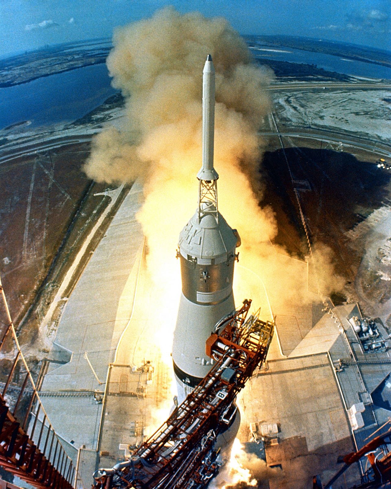
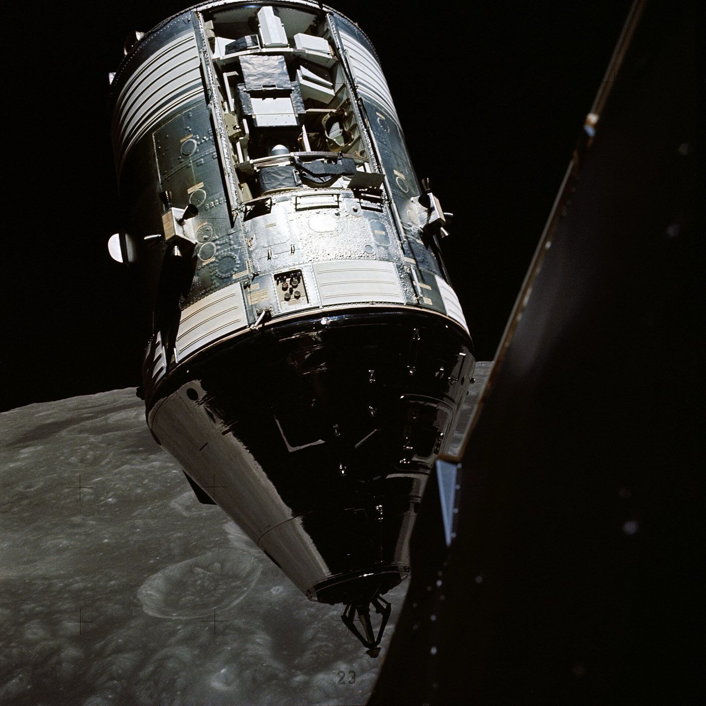
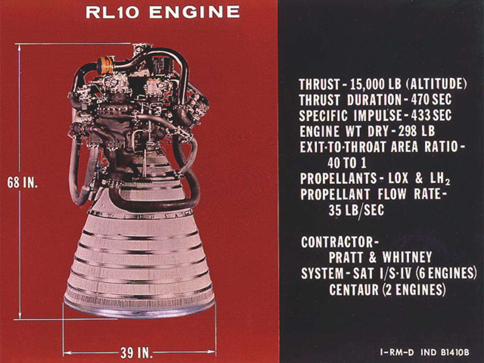
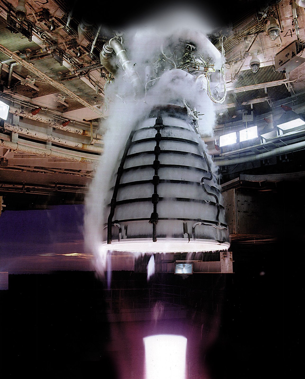
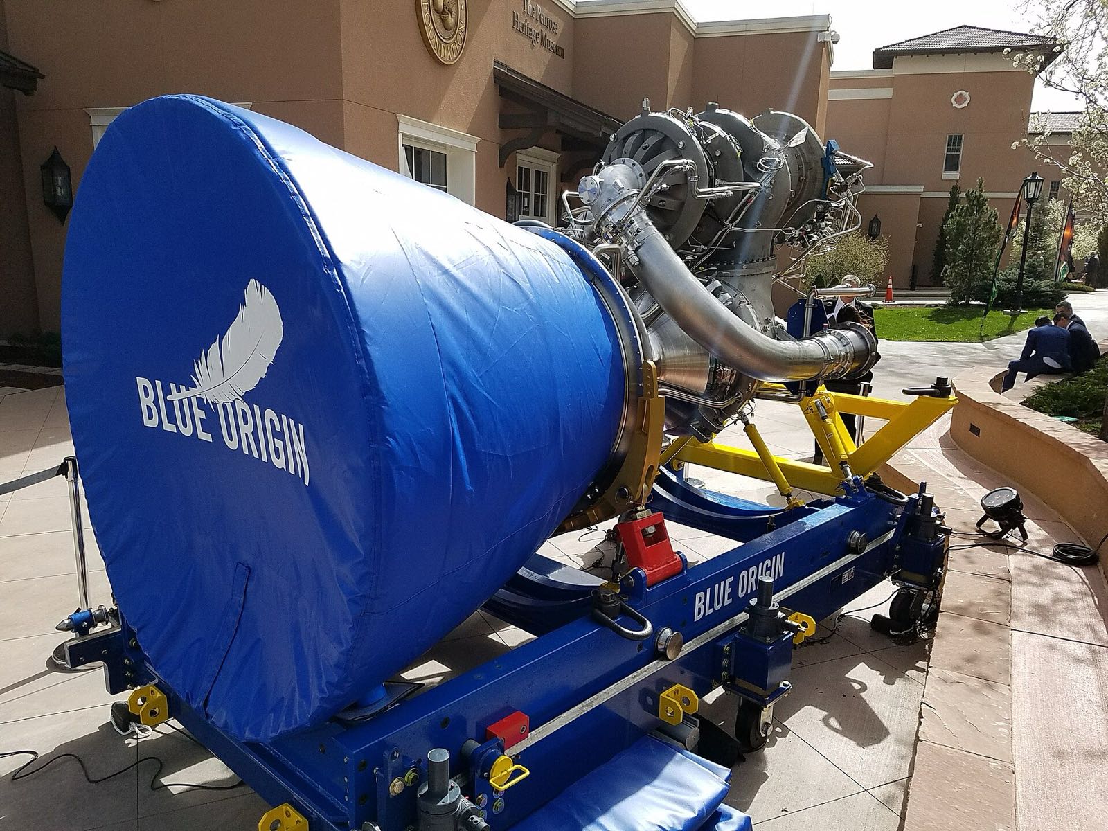
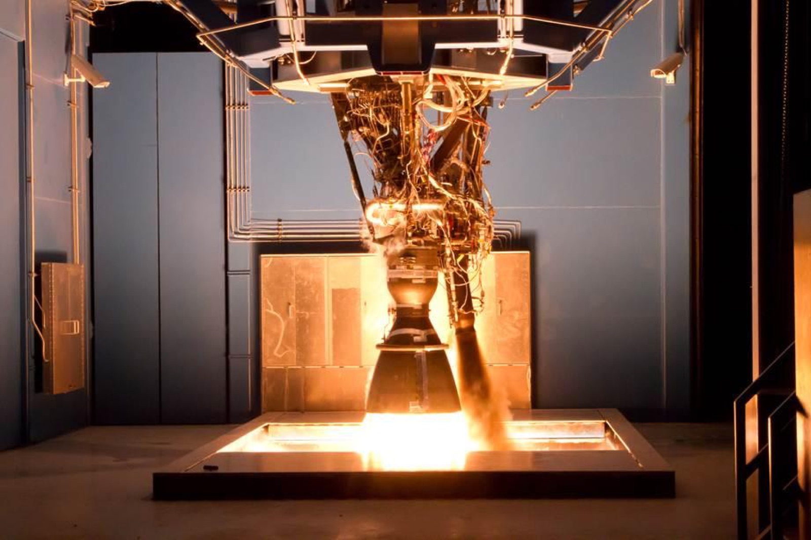
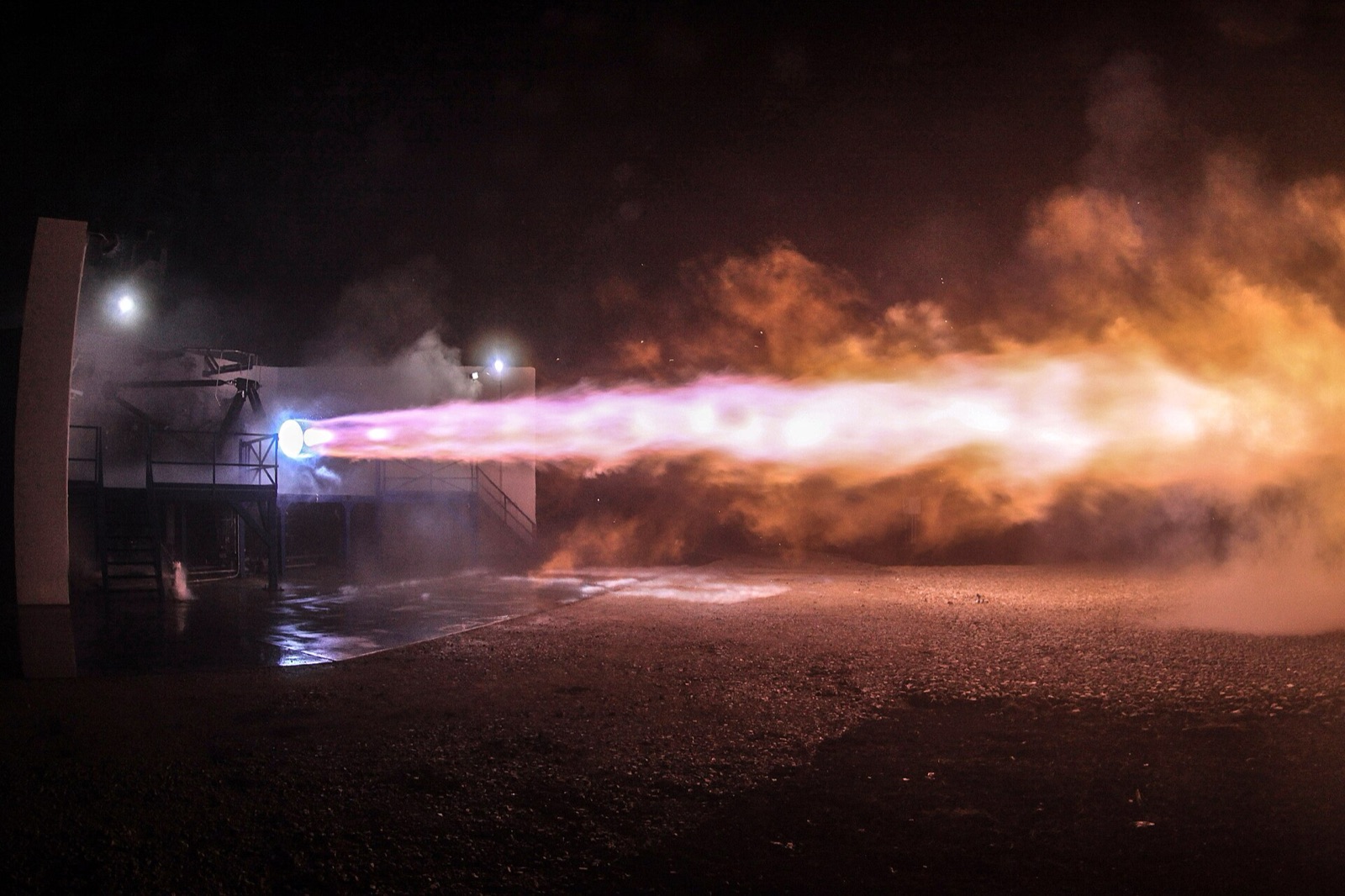
The J-2 is a liquid hydrogen and liquid oxygen engine that Rocketdyne developed for NASA under a contract dated 1 September 1960. Five J-2 engines powered the second stage of the Saturn V. A single J-2 powered the third stage, which restarted in Earth orbit to send Apollo toward the Moon. Rocketdyne delivered 152 production engines.
The chamber wall is made of stainless-steel tubes brazed together, with liquid hydrogen running down 180 tubes and back up 360 to cool them. The first injector was copper and melted in development. The production injector has a porous sintered-metal face, and part of the fuel flows through it. The propellants also lubricate the pump bearings.
Application
Five J-2 engines powered the Saturn V second stage and one J-2 powered the third stage, which restarted in Earth orbit to send Apollo toward the Moon. The engine is a reference for early hydrogen-oxygen engine construction: a brazed stainless-steel tube chamber, a propellant-lubricated turbopump pair and a hydrogen-fed start tank.
Photos
No photos we are allowed to show yet. If you have a photo of this product and the right to share it, send it to us.
How it is built
Chamber and nozzle
The chamber body is a set of longitudinal stainless-steel tubes, brazed together and held by external stiffening bands. Hydrogen runs down 180 tubes and back up 360, cooling the wall on the way. Exhaust from the turbines is dumped into the nozzle at the point where the 180 tubes split into 360.
Chamber tubes
Tube circuit (180 down, 360 up)
External stiffening bands
Turbine exhaust injection into the nozzle
Injector and igniter
The first injector had a flat copper face. It melted in development, and the vaporised copper turned the exhaust plumes green. The production face is Rigi-Mesh, a porous screen of sintered metal, and part of the fuel flows through it to keep it cool. An igniter with two spark plugs lights the chamber.
Injector face (production)
Original injector (flat-faced)
Augmented spark igniter chamber
Augmented spark igniter spark plugs (two)
Igniter fuel line
Turbopumps
The fuel pump is a high-speed axial machine with an inducer and a seven-stage rotor and stator. Its design came from pumps used in nuclear rocket programmes. The oxygen pump is a single-stage centrifugal pump. Gas from the gas generator drives the fuel turbine and then the oxygen turbine, and the propellants lubricate the bearings.
Fuel turbopump (axial, self-lubricated)
Fuel pump rotor
Oxidizer turbopump (centrifugal)
Series turbine drive
Propellant-lubricated bearings
Gas generator and start system
A small combustion chamber with two spark plugs, the gas generator, makes the hot gas that spins the turbines. To start the engine, cold hydrogen from a start tank is discharged through both turbines. A heat exchanger in the turbine exhaust duct boils liquid oxygen to pressurise the oxygen tank.
Gas generator
Hydrogen start tank
Heat exchanger (LOX tank pressurisation)
Valves, seals and gimbal
The main fuel valve and the main oxygen valve are both butterfly valves, and the oxygen valve is spring loaded closed. Teflon-coated seals keep the hydrogen in at duct flanges and pipe joints. On the third stage, two hydraulic actuators swivel the engine.
Main fuel valve
Main oxidizer valve
Hydrogen seals at duct flanges and pipe joints
Gimbal actuators (two)
Where the parts areNumber of parts we have listed in each group
Injector and igniter6
Thrust chamber5
Turbopumps5
Gas generator, heat exchanger and start system3
Valves and seals3
Propellants2
Gimbal (S-IVB installation)1
What it is made of
Stainless steel
The brazed chamber tubes, and the igniter fuel line with its braid-covered flexible bellows.
Rigi-Mesh sintered metal screen
The face of the production injector. Part of the fuel flows through it to cool it.
The original flat-faced injector, which melted during development.
Teflon-coated seals
Seals at duct flanges and pipe joints that keep the hydrogen contained.
Liquid hydrogen
The fuel. It cools the chamber tubes and, with the liquid oxygen, lubricates the pump bearings.
The materials by familyHow many of the parts that name a material use each one
Stainless steel3
Other3
Copper1
Polymers and foams1
How it connects to other things
Five J-2 engines sat at the back end of the Saturn V second stage, the S-II, and the four outer ones swivelled. One more powered the third stage, the S-IVB. The J-2 first flew on 26 February 1966, on a Saturn IB second stage, as part of AS-201. Rocketdyne built it, and Moog Industries made the third-stage gimbal actuators. Its fuel pump was derived from Rocketdyne's nuclear rocket programme pumps.
stainless steel. Here: Chamber tubes; Igniter fuel line and more. There: Pintle tip, original; Flow-control valve bellows and more.
Copper. Here: Original injector (flat-faced). There: Pintle tip, copper-slug version.
What we do not know
Published accounts name few of the metals. The grade of the stainless steel, the braze alloy and the alloy of the injector face are missing, as are the metals of the pump rotors and housings, the valve bodies, the gas generator and the hydrogen start tank. Rigi-Mesh is a trade name, not an alloy.
The detailed data
What is written above is built from these numbers and quotes. Each row links to the page it was taken from. Get all of it as JSON, or ask our MCP server.
Features
Fuel turbopump is an axial machine derived from nuclear rocket programme pumps
Cold hydrogen from a start tank spins both turbines at engine start
Augmented spark igniter with two spark plugs lights the chamber
Turbopump bearings are lubricated by the propellants, with no separate lubrication system
Turbine exhaust is dumped into the nozzle at the point where the tube circuit splits two up for one down
Fuel runs down 180 tubes and back up 360 tubes in the regeneratively cooled chamber
The original copper injector melted in development and was replaced by a porous sintered-metal face
Apollo 6 anomaly was traced to the bellows in the augmented spark igniter fuel line
Coffman credits J-2 development experience for later Shuttle main engine, RS-68 and X-33 engine work
Specifications
What
Value
Vacuum thrust
Up to 230,000 lbf
Cycle
Open-cycle gas generator
Specific impulse
425 s
Chamber pressure
A little over 700 psia
Mixture ratio
5.5:1 oxidizer to fuel
Alternate mixture ratio
4.5:1
Nozzle area ratio
27.5:1
Propellants
Liquid oxygen and liquid hydrogen
Restart
Restartable in space
Engines per vehicle (S-II)
5 on the Saturn V second stage
Engines per vehicle (S-IVB)
1 on the Saturn V third stage
Production
152 production engines
Development contract
1 September 1960 (Rocketdyne)
First flight
26 February 1966, AS-201 (Saturn IB second stage)
Materials in detail
Each material named in the sources: where it is used here, which other products use it, and its key numbers when its material page exists.
stainless steel (grade not stated)
stainless-steel
Used in 3 partsChamber tubes · Igniter fuel line · Igniter fuel-line bellows
Stage use, cycle and layout are sourced from NASA SP-2009-4545 and EngineHistory.org. Stated materials: brazed stainless-steel chamber tubes, stainless-steel igniter fuel line and bellows, a sintered-metal injector face, the original copper injector and Teflon-coated hydrogen seals. Pumps, valves, gas generator and start tank are listed without a material.