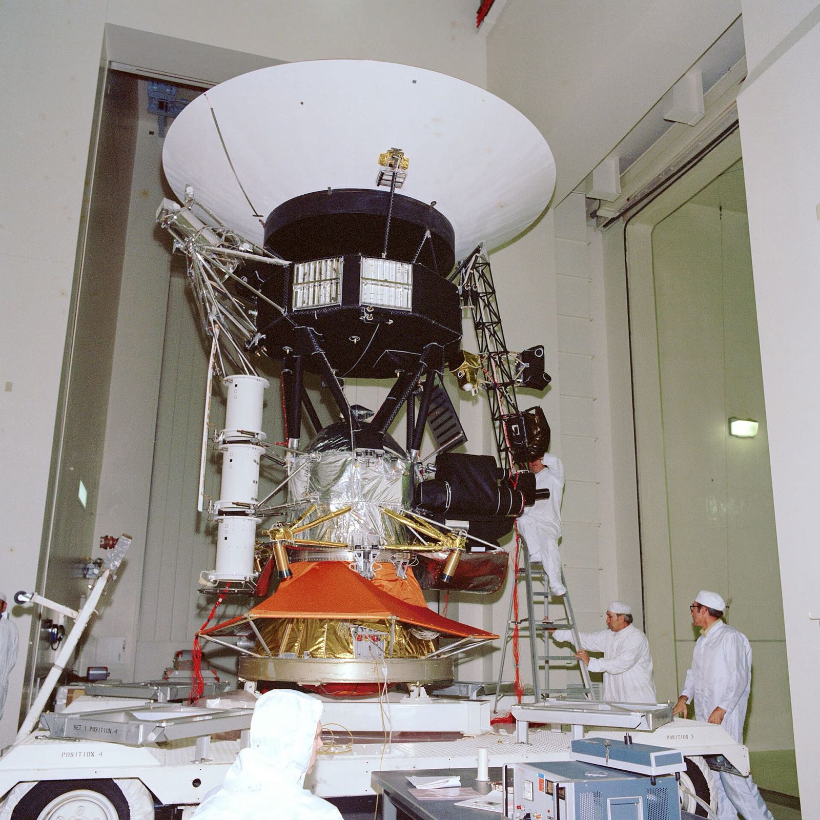
A Voyager spacecraft with its high-gain antenna and science boom undergoing testing at JPL in November 1976
NASA / JPL

Voyager spacecraft (Voyager 1 and 2)

The Voyager probes are the most distant human-made objects, and each carries a golden record of Earth.

Platforms and buses
Product IDnasa-voyager
Voyager 2 launch
20 August 1977
Voyager 1 launch
5 September 1977
Voyager 1 mass
1,592 lb (721.9 kg)
High-gain antenna
3.7 m
Golden record
12 in (30 cm) disc
Instruments still active
three of 11 science experiments remain active on each spacecraft

In short

Voyager 1 and Voyager 2 are twin NASA probes. Voyager 2 launched on 20 August 1977 and Voyager 1 on 5 September. Both flew past the outer planets and are now in interstellar space. NASA's Jet Propulsion Laboratory built them and manages the mission.

Each probe carries a golden record, a 30 cm disc of gold-plated copper holding sounds and images of Earth, as a message for anyone who might find it. Three radioisotope generators power each probe. They turn the heat of decaying plutonium-238 into electricity.

Application

Two NASA probes that flew past the outer planets and are now in interstellar space. They run on radioisotope generators and each carries a golden record of sounds and images of Earth. They are the most distant human-made objects.

How it is built

The golden record

The disc is gold-plated copper, 12 inches (30 cm) across. Each record travels in a protective aluminium jacket, together with a cartridge and a needle. The aluminium cover has an ultra-pure sample of uranium-238 electroplated on it.

  • Record disc
  • Record cover
  • Record protective jacket
  • Uranium-238 sample on cover
  • Cartridge and needle

Radioisotope power

Each generator unit is 40.6 cm across and 50.8 cm long, weighs 39 kg and sits in a beryllium case. The fuel is plutonium-238 oxide, whose decay heat is turned into electricity. A boom holds the generators away from the science instruments.

  • RTG outer case
  • RTG heat source fuel
  • RTG boom

Bus and booms

The body is a ten-sided bus, 47 cm high and 1.78 m across, with an electronics bay in each side. Most instruments sit on a science boom about 2.5 m long, and a separate 13 m boom carries the magnetic-field instruments. Two 10 m whip antennas also extend from the spacecraft.

  • Ten-sided bus (decahedral, 47 cm high, 1.78 m flat to flat)
  • Ten electronics bays
  • Science boom (about 2.5 m)
  • Magnetometer boom (13 m)
  • Two 10 m whip antennas (plasma wave and radio astronomy)

Thrusters

Liquid hydrazine fuels the thrusters, all of which Aerojet Rocketdyne developed. A rubber diaphragm sits in the fuel tank. Voyager engineers fired the four trajectory correction thrusters for the first time in 37 years.

  • Attitude-control hydrazine thrusters (two branches)
  • Trajectory correction maneuver (TCM) thrusters (x4)
  • Hydrazine propellant
  • Fuel tank diaphragm
Where the parts areNumber of parts we have listed in each group
  • Science instruments11
  • Telecommunications10
  • Bus and structure8
  • Computers and attitude control6
  • Golden Record5
  • Propulsion5
  • Radioisotope power4
  • Radioisotope power (3 RTGs)1
  • Launch-phase hardware1

What it is made of

  • Gold-plated copper

    The golden record disc, 12 inches (30 cm) across.

  • Aluminium

    The record's cover and its protective jacket.

  • Uranium-238

    An ultra-pure sample electroplated on the record's aluminium cover.

  • Plutonium-238 oxide

    The fuel in the radioisotope generators. Its decay heat is converted to electrical power.

  • Beryllium

    The outer case of each radioisotope generator.

  • Hydrazine

    The liquid fuel for the thrusters.

The materials by familyHow many of the parts that name a material use each one
  • Other3
  • Aluminium2
  • Copper1
  • Beryllium1
  • Semiconductors1
  • Polymers and foams1

How it connects to other things

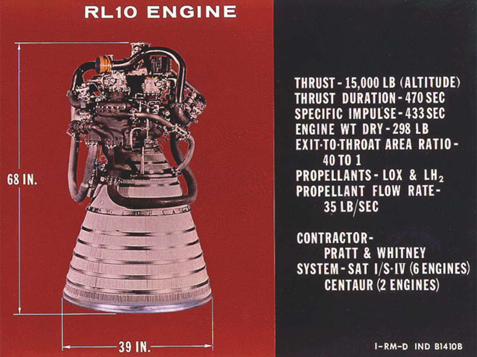
Both probes left Cape Canaveral in 1977 on Titan IIIE-Centaur rockets. Each rocket had two solid boosters, an Aerojet LR87-11 engine in the first stage and an LR91-11 in the second, and a Centaur upper stage with two RL10A-3 engines. Aerojet Rocketdyne also developed the probes' own thrusters. The Jet Propulsion Laboratory built both, and their cameras are modified versions of designs flown on earlier Mariner missions.

Engines

  • Star 37E solid rocket motor

    kick stage flown on both launches but counted with the payload

Launched on

  • Titan IIIE-Centaur (Voyager 1 on TC-6, Voyager 2 on TC-7)

    Centaur D-1T upper stage; launched from Cape Canaveral in 1977

  • LR87-11 engine (Titan IIIE core first stage)

    one Aerojet LR87-11 on the first stage

  • LR91-11 engine (Titan IIIE core second stage)

    one Aerojet LR91-11 on the second stage

  • RL10 engine

    Aerojet Rocketdyne

    Centaur D-1T used two RL10A-3 engines from Pratt & Whitney; RL10 hub is ula-rl10

  • UA1205 solid rocket boosters (two, Titan IIIE)

    zero-stage solids from Chemical Systems Division of United Technologies

Builds on

  • Mariner program (Mariner Jupiter/Saturn)

    the imaging cameras are a modified Mariner slow-scan vidicon design

Made or supplied by

  • Aerojet Rocketdyne

    developed all of Voyager's hydrazine thrusters (MR-103 family)

Operated by

  • Jet Propulsion Laboratory (Caltech)

    manages the mission for NASA and built the spacecraft

Products that use the same materials

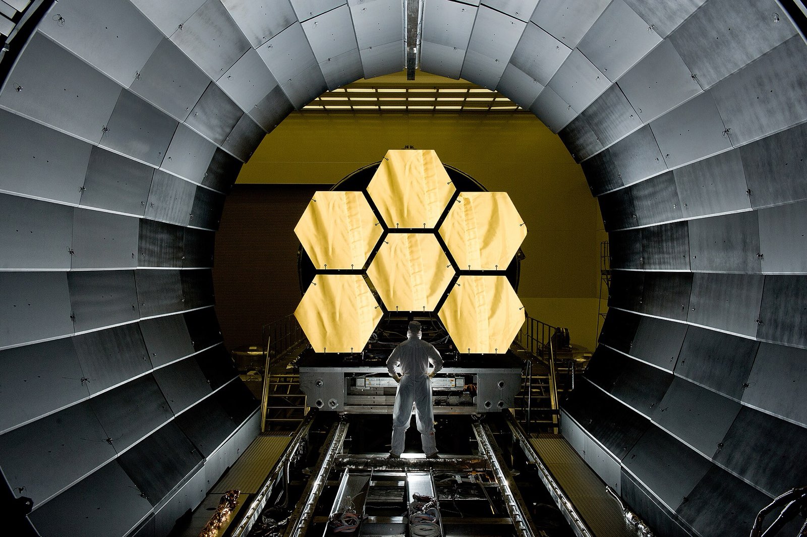
  • James Webb Space Telescope

    NASA

    AluminiumBerylliumhydrazine
    Where each one is used

    Aluminium. Here: Record cover; Record protective jacket. There: Sunshield layer coating (all 5 layers).

    Beryllium. Here: RTG outer case. There: Primary mirror segment substrate.

    hydrazine. Here: Hydrazine propellant. There: Monopropellant engine fuel.

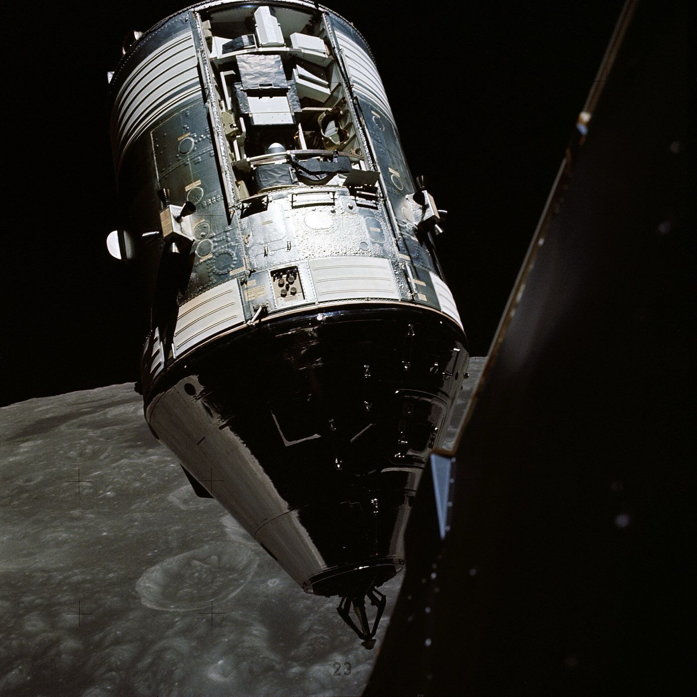
  • Apollo Command and Service Module

    North American Aviation

    AluminiumBeryllium
    Where each one is used

    Aluminium. Here: Record cover; Record protective jacket. There: Radial beams; Crushable ribs (x4) and more.

    Beryllium. Here: RTG outer case. There: Inertial measurement unit (IMU).

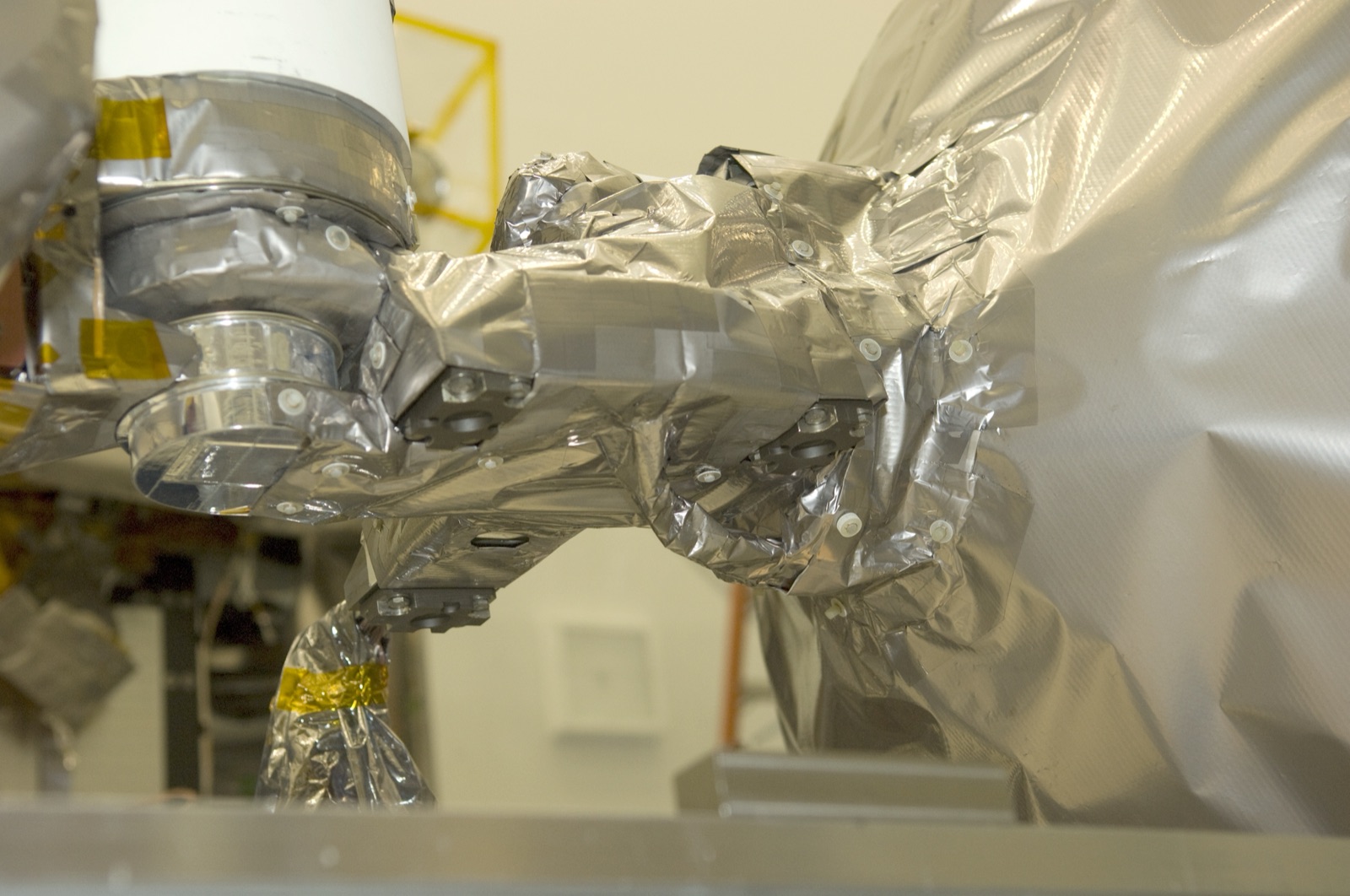
  • Lunar Reconnaissance Orbiter (LRO)

    NASA Goddard Space Flight Center

    Aluminiumhydrazine
    Where each one is used

    Aluminium. Here: Record cover; Record protective jacket. There: Primary structure (heating/cooling panel, edge members, fittings, brackets); Optical-bench heater aluminum tape and more.

    hydrazine. Here: Hydrazine propellant. There: Propellant.

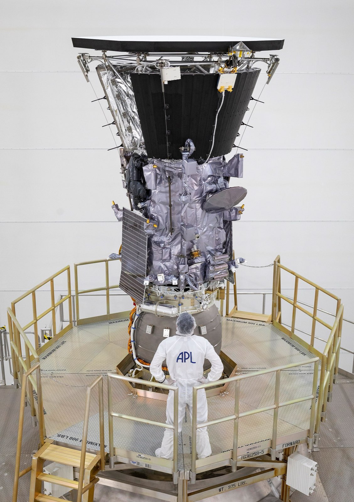
  • Parker Solar Probe

    NASA / Johns Hopkins APL

    Aluminiumhydrazine
    Where each one is used

    Aluminium. Here: Record cover; Record protective jacket. There: Radiator fins.

    hydrazine. Here: Hydrazine propellant. There: MR-111C hydrazine thrusters (x12).

What we do not know

Several things are still unknown. The materials of the bus, the booms, the antenna dish and the thermal blankets are not given. Nor are the builders of the generators, computers, transmitters and instruments named, and a mass is given only for Voyager 1.

The detailed data

What is written above is built from these numbers and quotes. Each row links to the page it was taken from. Get all of it as JSON, or ask our MCP server.

Features

  • Carries a golden record message with sounds and images of Earth
  • Bus has ten sides, each with an electronics bay

Specifications

WhatValue
Voyager 1 launch5 September 1977
Voyager 2 launch20 August 1977
Voyager 1 mass1,592 lb (721.9 kg)
Power at launchThree MHW-RTGs, about 158 We each
Power in 2023225 We from the RTGs
High-gain antenna3.7 m
Golden record12 in (30 cm) disc
Bus size47 cm high, 1.78 m flat to flat
Science boom lengthabout 2.5 m
Magnetometer boom length13 m
RTG unit size and mass40.6 cm diameter, 50.8 cm long, 39 kg
Initial RTG powerabout 470 W at 30 V DC
DownlinkX-band at 160 bits/s normally, 1.4 kbps for plasma-wave playback; S-band uplink at 16 bits/s
High-gain antenna reflector3.66 m
Prime-mission payload10 instruments, 11 investigations including radio science
Active instrumentsthree of 11 science experiments remain active on each spacecraft
Launch vehicle, Voyager 2Titan IIIE-Centaur (TC-7 / Titan no. 23E-7 / Centaur D-1T)

Materials in detail

Each material named in the sources: where it is used here, which other products use it, and its key numbers when its material page exists.

Every part we have

Only the record and RTG fuel materials are stated by NASA; the bus and dish materials are not. Components, suppliers and links were added from public sources. A material is left blank where no source states it.

Material IDs

gold-plated-copperaluminiumuranium-238plutonium-238-oxideberylliumsilicon-germaniumhydrazinerubber-diaphragm-unspecified
Golden Record5
Radioisotope power (3 RTGs)1
PartMaterialFinish and standardMade by
RTG heat source fuel“The heat source radioisotopic fuel is Plutonium-238 in the form of the oxide Pu02.” plutonium-238 oxideplutonium-238-oxide — —
Bus and structure8
PartMaterialFinish and standardMade by
Ten-sided bus (decahedral, 47 cm high, 1.78 m flat to flat)carries the engineering subsystems and science instruments; its z-axis points the dish at Earth“Each Voyager consisted of a decahedral bus, 47 cm in height and 1.78 m across from flat to flat.” Not said — Supplier: Jet Propulsion Laboratory
Ten electronics baysone compartment on each side of the bus, housing electronic assemblies (bay 1 holds the radio transmitters)“Each of the ten sides of the bus contains a compartment (a bay) that houses various electronic assemblies.” Not said — —
Science boom (about 2.5 m)carries the scan platform and the plasma and charged-particle detectors“The major portion of the science instruments were mounted on a science boom extending out some 2.5 m from the spacecraft.” Not said — —
Scan platformsteerable platform for the imaging and spectroscopic remote-sensing instruments“At the end of the science boom was a steerable scan platform on which were mounted the imaging and spectroscopic remote sensing instruments.” Not said — —
Magnetometer boom (13 m)holds the magnetometers away from the bus on the side opposite the science boom“The magnetometers were located along a separate boom extending 13 m on the side opposite the science boom.” Not said — —
RTG boomdeployable boom that holds the three RTGs end to end“A third boom, extending down and away from the science instruments, held the spacecraft's radioisotope thermoelectric generators (RTGs).” Not said — —
Optical calibration target plateflat rectangle of known colour and brightness for calibrating the scan-platform instruments“The target plate is a flat rectangle of known color and brightness, fixed to the spacecraft” Not said — —
Two 10 m whip antennas (plasma wave and radio astronomy)two long antennas at right angles, shared by the PWS and PRA experiments“Two 10 m whip antennas (used for the plasma wave and planetary radio astronomy investigations) also extended from the spacecraft” Not said — —
Radioisotope power4
PartMaterialFinish and standardMade by
RTG outer caseholds each of the three MHW-RTG units (40.6 cm diameter, 50.8 cm long, 39 kg)“Each RTG unit, contained in a beryllium outer case, was 40.6 cm in diameter, 50.8 cm in length, and weighed 39 kg.” berylliumberyllium — —
RTG thermoelectric converter (silicon-germanium couples)turns the decay heat of plutonium-238 oxide into electricity“Conversion of the decay heat of the plutonium to electrical power uses 312 silicon-germanium” silicon-germanium (SiGe) thermoelectric couplessilicon-germanium — —
RTG gas pressure venting system and temperature transducersvent gas from the heat source and report RTG temperatures“a gas pressure venting system, temperature transducers, connectors, a heat rejecting cylindrical container, and bracketry” Not said — —
Three MHW-RTGs (electrically parallel)central power sources; about 470 W at launch“Three radioisotope thermoelectric generator units (RTGs), electrically parallel-connected, are the central power sources for the mission module.” Not said — —
Computers and attitude control6
PartMaterialFinish and standardMade by
Computer Command Subsystem (CCS)stores commands and issues them at set times; holds fault-detection and sequencing routines“The Computer Command Subsystem (CCS) was responsible for storing commanding for the other two computers and issuing the commands at set times.” Not said — —
Attitude and Articulation Control Subsystem (AACS)controls spacecraft orientation, keeps the dish on Earth and moves the scan platform“The Attitude and Articulation Control Subsystem (AACS) controls spacecraft orientation, maintains the pointing of the high gain antenna towards Earth” Not said — —
Flight Data Subsystem (FDS)controls the instruments, their configuration and telemetry rates“The Flight Data Subsystem (FDS) controlled the instruments, including changes in configuration (state) or telemetry rates.” Not said — —
Star trackers and Sun sensorscelestial references for pointing; redundant units“The AACS included redundant star trackers and Sun sensors as well.” Not said — —
Gyroscopesgyro-referenced attitude control“use celestial or gyro referenced attitude control to maintain pointing of the high-gain antennas toward Earth” Not said — —
Digital tape recorder (DTR)stores data for later transmission“Data could be stored for later transmission to Earth through the use of an on-board digital tape recorder.” Not said — —
Propulsion5
PartMaterialFinish and standardMade by
Attitude-control hydrazine thrusters (two branches)small thrusters that roll the spacecraft and keep the dish pointed at Earth; two redundant branches“All of Voyager's thrusters were developed by Aerojet Rocketdyne.” Not said — Supplier: Aerojet Rocketdyne
Trajectory correction maneuver (TCM) thrusters (x4)four thrusters on the back of the spacecraft, used at planetary flybys and again since 2017 for pointing“Voyager engineers fired up the four TCM thrusters for the first time in 37 years” Not said — Supplier: Aerojet Rocketdyne
Hydrazine propellantliquid monopropellant turned to gas in the thrusters' catalyst beds“The thrusters are fueled by liquid hydrazine” hydrazine (liquid)hydrazine — —
Fuel tank diaphragmrubber diaphragm in the fuel tank, source of the silicon dioxide that has clogged thruster tubes“a rubber diaphragm in the spacecraft’s fuel tank” rubber (diaphragm; compound not stated)rubber-diaphragm-unspecified — —
Thruster fuel tubes and catalyst bedstubes direct hydrazine to catalyst beds where it becomes gas“The clogged tubes are located inside the thrusters and direct fuel to the catalyst beds” Not said — —
Telecommunications10
PartMaterialFinish and standardMade by
High-gain antenna main reflector (3.66 m)main dish of the S/X-band high-gain antenna“For the HGA, the SXA has a 3.66-m diameter main reflector, a frequency selective surface (FSS) subreflector, and S-band and X-band feeds.” Not said — —
Frequency selective surface (FSS) subreflectorreflects X-band for the Cassegrain path and passes S-band to the prime-focus feed“The main reflector, FSS (transparent at S-band), and S-band feed form a prime focus radiator.” Not said — —
S-band low-gain antennamounted on the back of the S-band feed structure; no longer used for downlink“The LGA is mounted on the back of the S-band feed structure.” Not said — —
S-band receivers (redundant pair)double-conversion receivers that lock to the uplink and generate the coherent downlink“The received carrier frequency controls the generation of the coherent downlink at both S- and X-band” Not said — —
S-band excitersdrive the S-band amplifier and supply the frequency reference to the X-band exciter“The S-EXC provides RF drive to the S-band power amplifier and a frequency reference to the X-EXC.” Not said — —
S-band power amplifiers (TWTA and solid-state)only one of the two is powered at a time“Only one S-band power amplifier, either the S-TWTA or the SSA, may be powered at a time” Not said — —
X-band exciters and traveling-wave tube amplifiersthe X-band downlink needs an S-band exciter, an X-band exciter and an X-TWTA“The X-band downlink requires an S-EXC, an X-EXC, and an X-TWTA.” Not said — —
Ultrastable oscillator (USO)preferred downlink frequency source; the Voyager 1 unit failed in 1992“The Voyager 1 USO failed in September 1992” Not said — —
Command detector units (CDU)detect command bits and send them with a clock to the CCS“The CDU outputs to the CCS the detected command bits and a clock signal derived from the command bit rate.” Not said — —
Telemetry modulation units (TMU)take high- and low-rate serial data from the FDS for the exciters“The TMU can receive both high- and low-rate, non-return-to-zero (NRZ), serial digital data from the FDS.” Not said — —
Science instruments11
PartMaterialFinish and standardMade by
Imaging Science Subsystem (ISS) wide-angle camera200 mm f/3 television-type camera with an 8-position filter wheel“a low resolution 200 mm wide-angle lens with an aperture of f/3” Not said — —
Imaging Science Subsystem (ISS) narrow-angle camera1500 mm f/8.5 higher-resolution television-type camera“a higher resolution 1500 mm narrow-angle f/8.5 lens” Not said — —
Infrared Interferometer Spectrometer and Radiometer (IRIS)thermometer, composition spectrometer and a separate reflected-light radiometer“measures radiation in two regions of the infrared spectrum” Not said — —
Photopolarimeter Subsystem (PPS)0.2 m telescope with filters and polarization analyzers for eight wavelengths“The Photopolarimeter Subsystem uses a 0.2 m telescope fitted with filters and polarization analyzers.” Not said — —
Ultraviolet Spectrometer (UVS)spectrometer for 40 to 180 nm light from atmospheres and interplanetary space“The Ultraviolet Spectrometer (UVS) covers the wavelength range of 40 nm to 180 nm” Not said — —
Planetary Radio Astronomy (PRA) receiverradio receiver on the shared V-shaped antennas“The PRA receiver covers two frequency bands, from 20.4 kHz to 1300 kHz and from 2.3 MHz to 40.5 MHz.” Not said — —
Plasma Wave Subsystem (PWS)plasma-wave receiver from 10 Hz to 56 kHz on the shared antennas“The PWS covers a frequency range of 10 Hz to 56 kHz.” Not said — —
Low-Energy Charged Particle experiment (LECP)two solid-state detector systems (LEPT and LEMPA) on a rotating platform“The Low-Energy Charged Particle experiment uses two solid-state detector systems mounted on a rotating platform.” Not said — —
Plasma Science (PLS) detectorsfour plasma detectors for low-energy ions and electrons“Three plasma detectors point in the direction of the Earth to observed solar wind flow and a fourth looks at a right angle” Not said — —
Cosmic Ray Subsystem (CRS)detects very energetic particles; highest sensitivity of the three particle detectors“The CRS looks only for very energetic particles in plasma, and has the highest sensitivity of the three particle detectors.” Not said — —
Magnetometer (MAG)measures the Sun's magnetic field with distance and time and the planetary fields“its primary job is to measure changes in the Sun's magnetic field with distance and time” Not said — —
Launch-phase hardware1
PartMaterialFinish and standardMade by
Star 37E solid kick motorextra upper stage that boosted each probe; counted as part of the payload, not the rocket“Star-37E stages were also used on the two Voyager launches” Not said — —

What the sources leave out

Bus structure material, high-gain antenna dish and subreflector materials, thermal blankets, thermoelectric converter material (silicon-germanium is not stated on the NASA pages read), and thruster propellant are not stated on the pages read. Mass is given for Voyager 1; Voyager 2 mass not read. More detail: Not published on the pages read: dish and subreflector materials, bus panel and boom materials, whip-antenna material, thermal blanket materials, the maker of the RTGs (General Electric is widely reported but no page read states it), the makers of the computers, the transmitters and the instruments (NASA lists current principal investigators only), the Star 37E maker, and the exact attitude-thruster count (16 total comes from Wikipedia; NASA/JPL say three branches and four TCM thrusters). The silicon-germanium converter material comes from Wikipedia, which cites Bennett 2006. The Centaur D-1T's two RL10A-3 engines link to the catalog RL10 hub; the Titan IIIE engines are not in the catalog. More detail: Not published on the pages read: dish and subreflector materials, bus panel and boom materials, whip-antenna material, thermal blanket materials, the maker of the RTGs (General Electric is widely reported but no page read states it), the makers of the computers, the transmitters and the instruments (NASA lists current principal investigators only), the Star 37E maker, and the exact attitude-thruster count (16 total comes from Wikipedia; NASA/JPL say three branches and four TCM thrusters). The silicon-germanium converter material comes from Wikipedia, which cites Bennett 2006. The Centaur D-1T's two RL10A-3 engines link to the catalog RL10 hub; the Titan IIIE engines are not in the catalog.
Where this comes from

11 pages from 5 websites

More space products

Collected from public pages and documents, checked 4 Nov 2026.

Published · Updated